Appearance
3. Building and Configuring Workflows
The Modelling Development Kit (MDK) is where you build and configure workflows using our library of models.
What You'll Learn
- Configure a traffic simulation workflow using pre-built components
- Create data connections between MDK workflows and DDK schemas
- Test and validate workflow execution
- Map variables for dynamic input handling
- Deploy workflows with event-driven triggers
Workflows are created and customised in the MDK. Use the workflow library to select templates, drag them into your workflow, and customise parameters (such as number of vehicles, simulation dates, or reaction times). The workflow outputs are stored in the objects you defined in the DDK. You can iterate, test, and refine workflows until you're satisfied with the results.
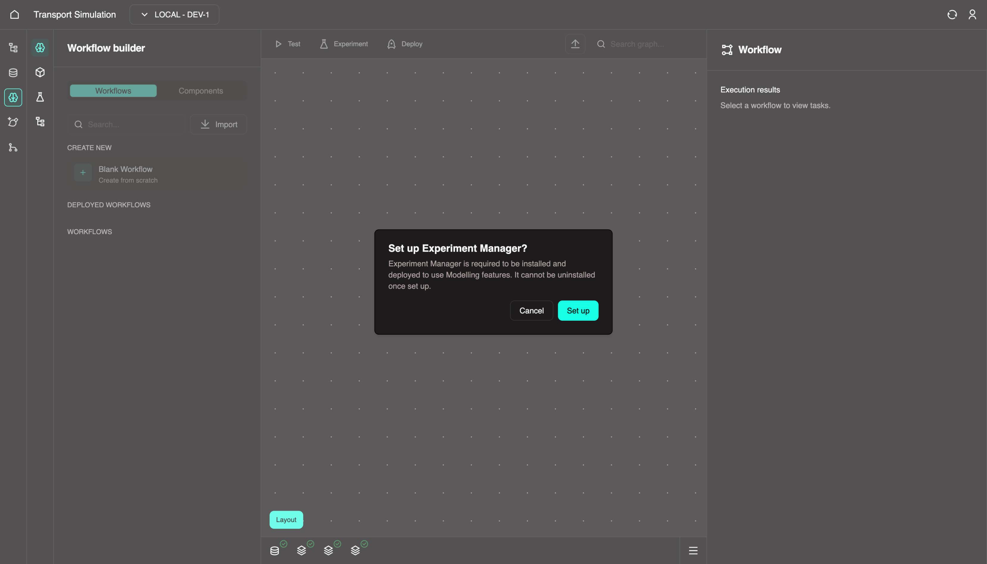
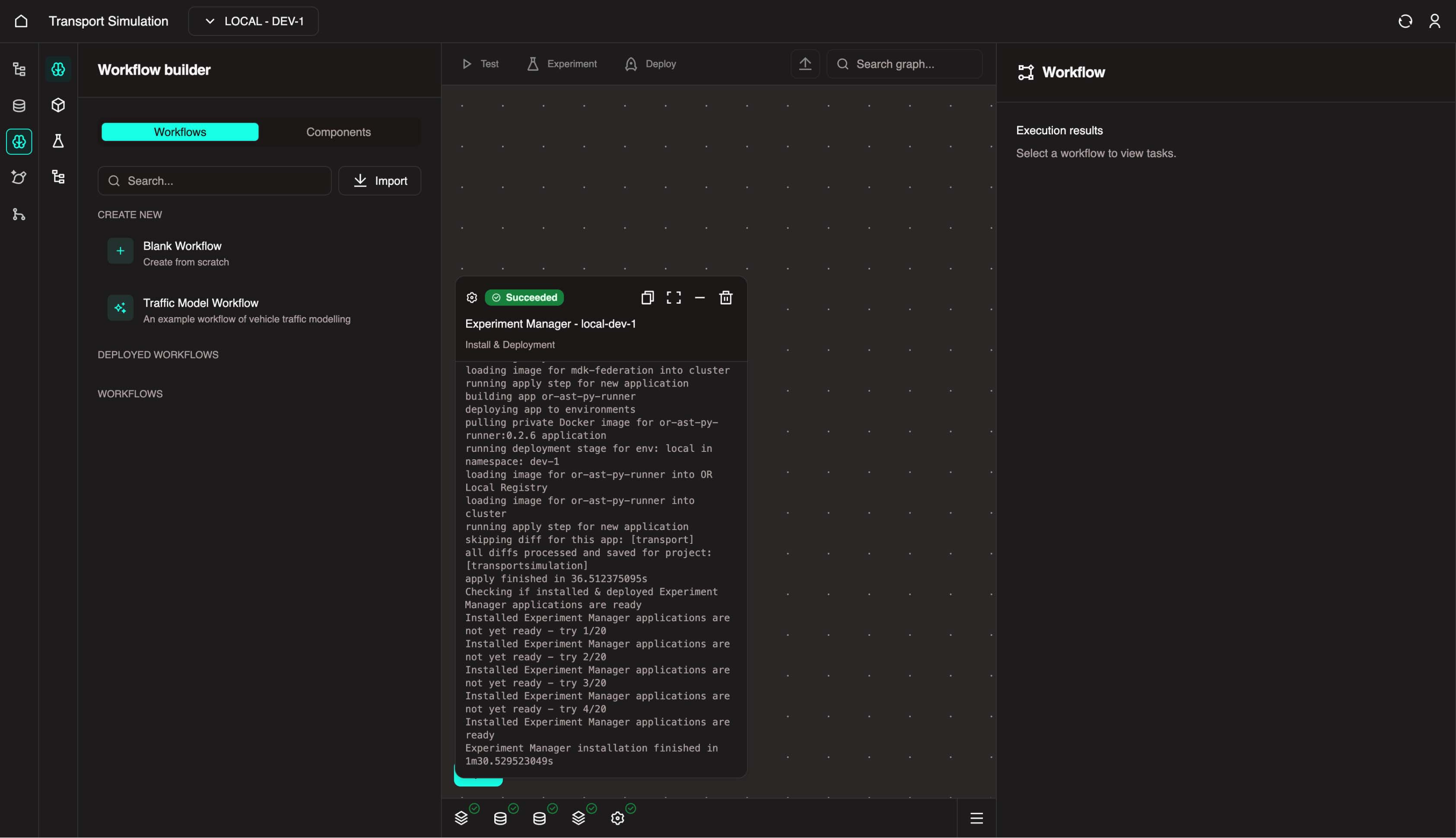
Before starting, navigate to the MDK and set up Experiment Manager. This can take a few minutes the first time you load up MDK.
3.1 Configuring Your Workflow
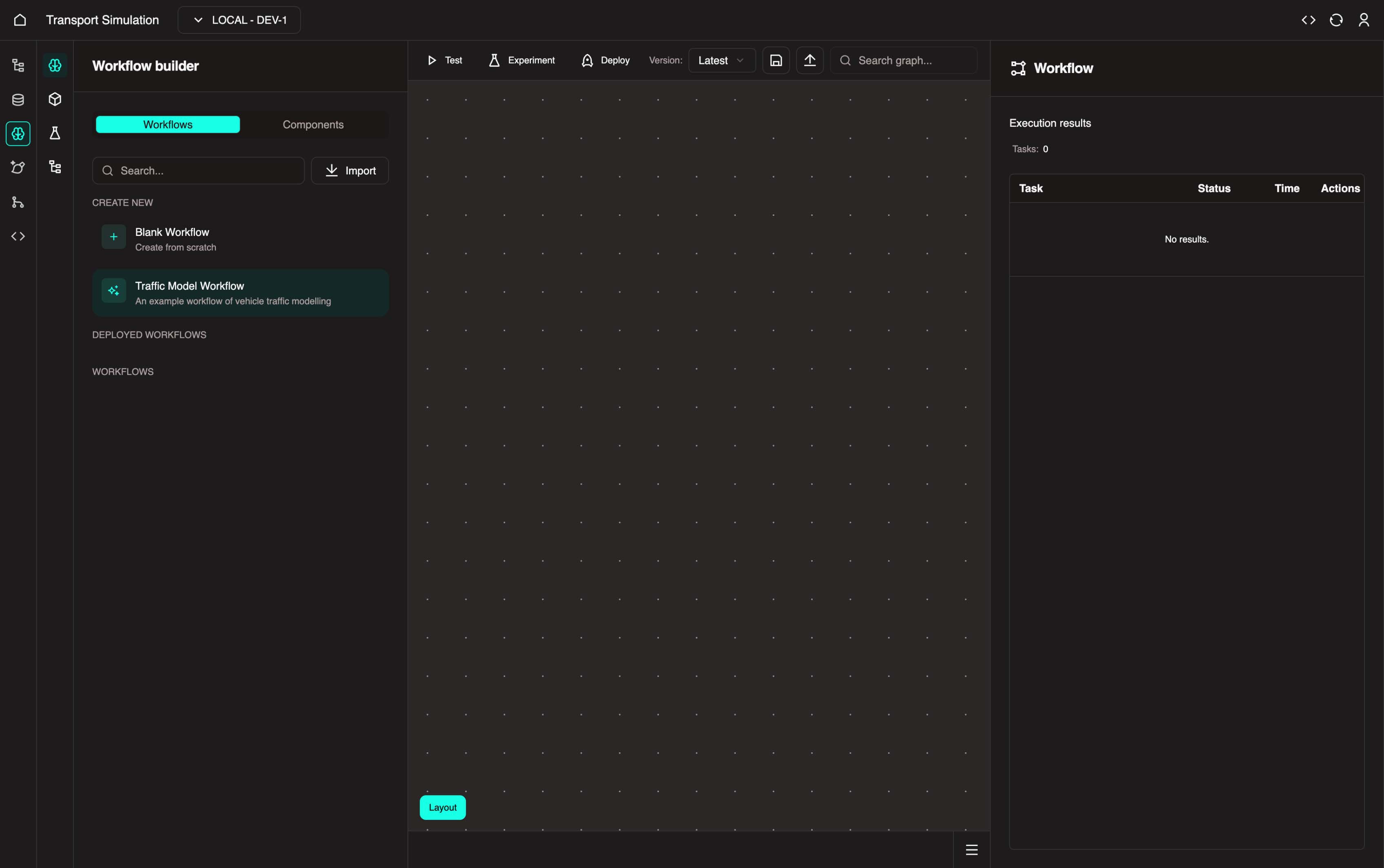
Since we're creating a traffic simulation, you can use a predefined model in OR instead of building from scratch.
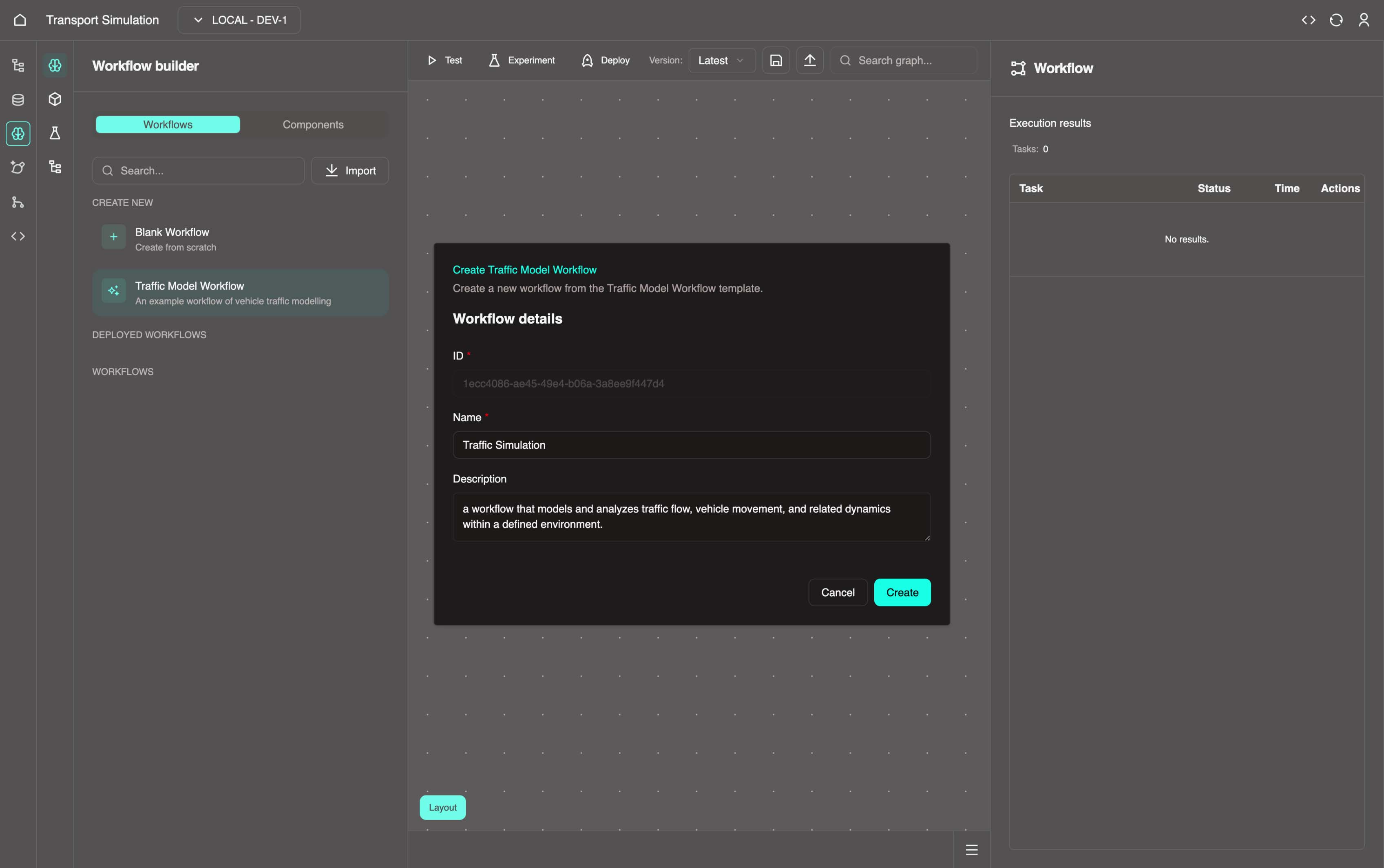
From the left panel, click Traffic Model Workflow.
Update the Name to
Traffic Simulationand click Create.
- Once created, select Traffic Simulation in the workflows panel to view it. This displays a default traffic network simulation workflow that we'll modify to align with our data schema.
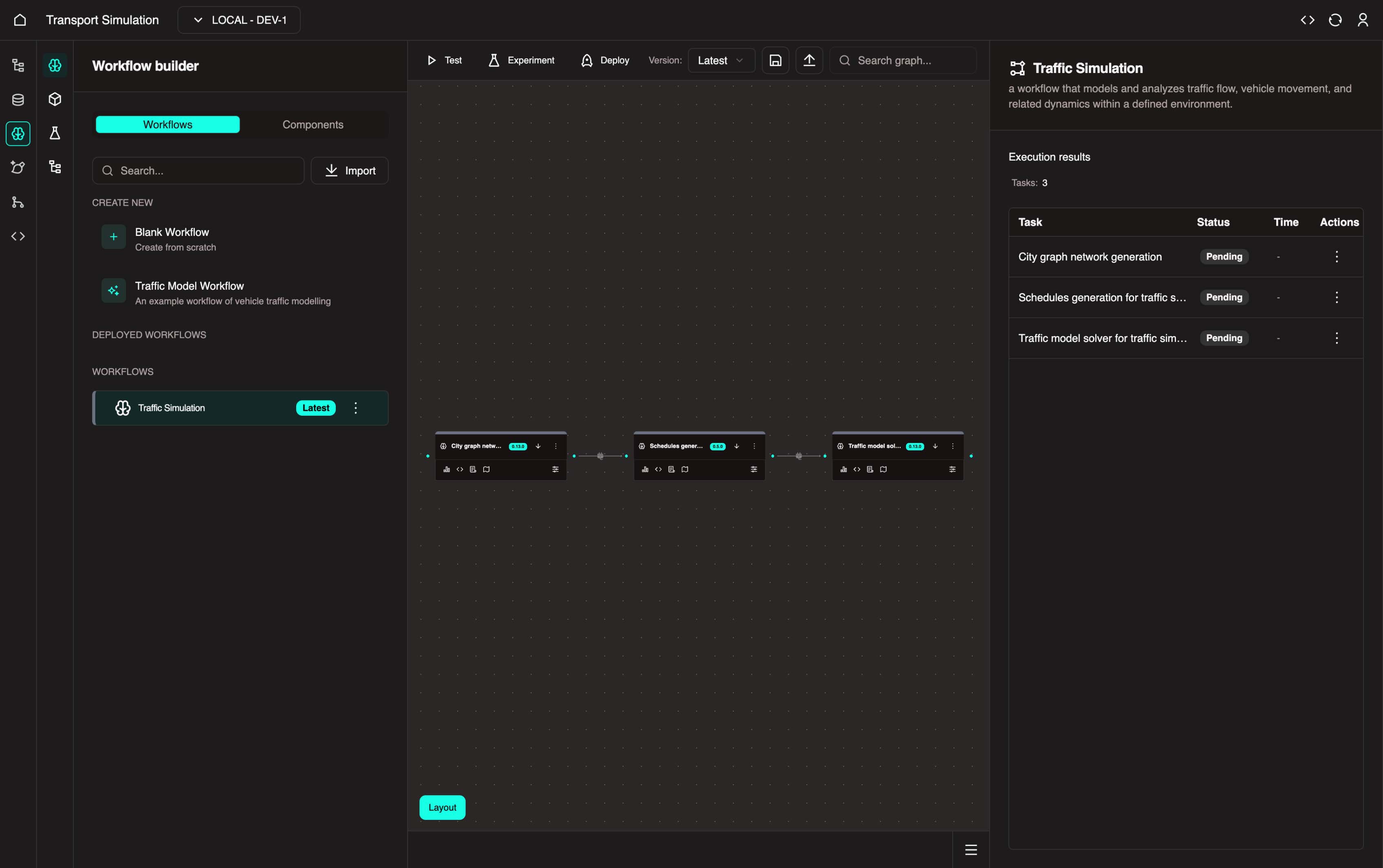
- In the visualiser, click the three dots on the City graph network generation node and select Delete. Confirm the deletion. This node requires a place name that doesn't match our DDK schema.
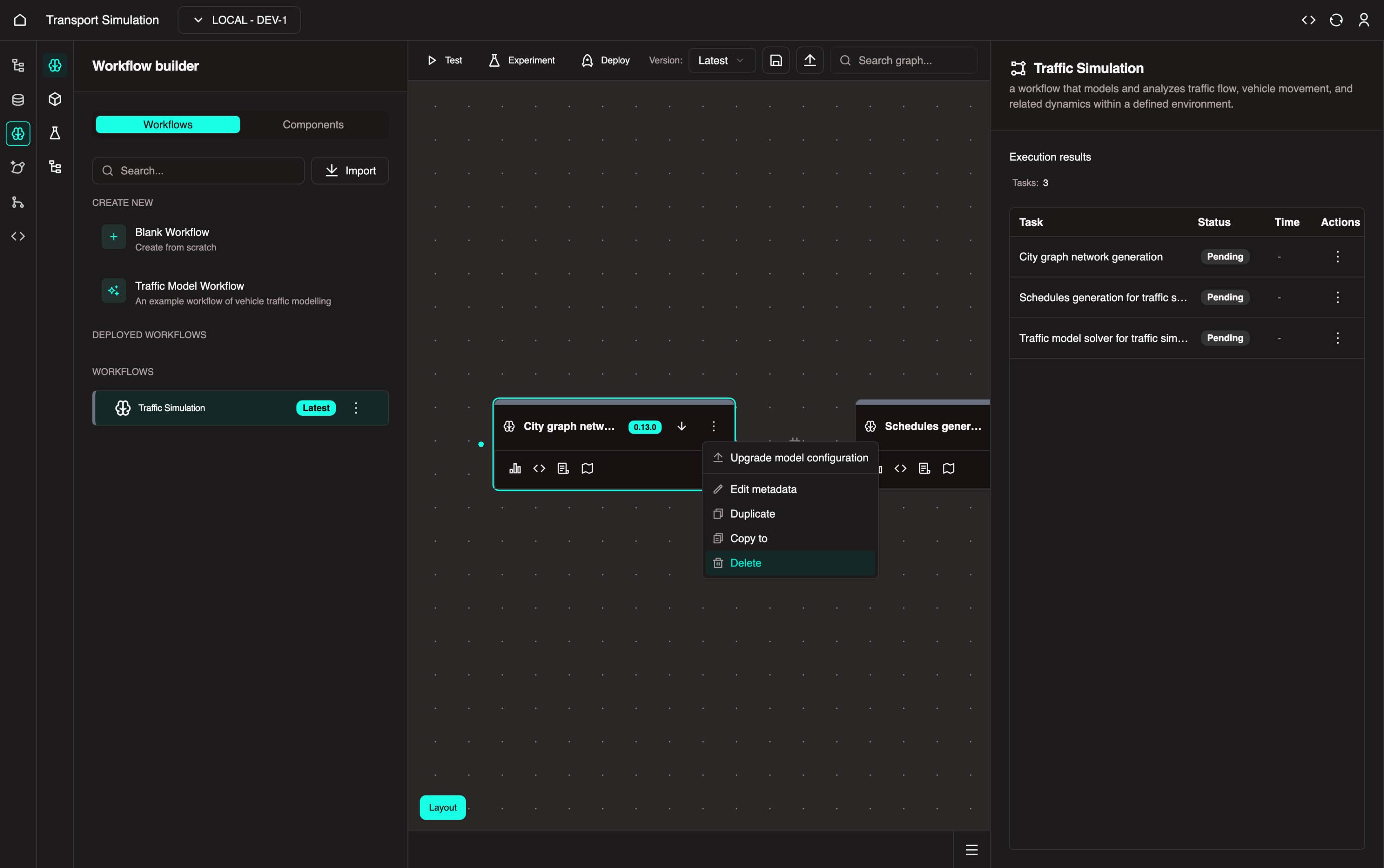
- After deletion:
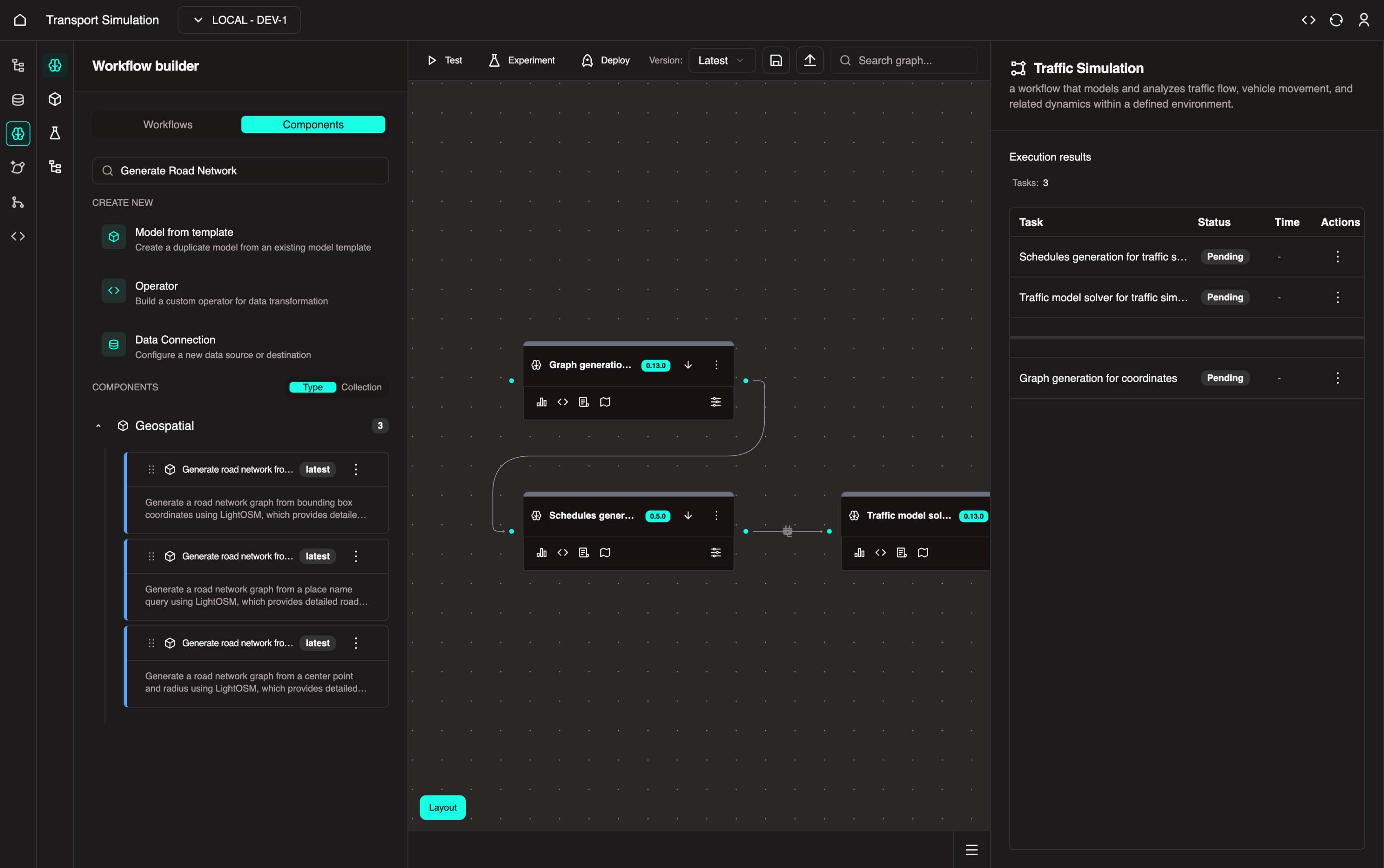
- Click the Components tab in the left panel
- Search for
Generate Road Network - Click the Geospatial collection and drag Generate road network from point and radius into the visualiser
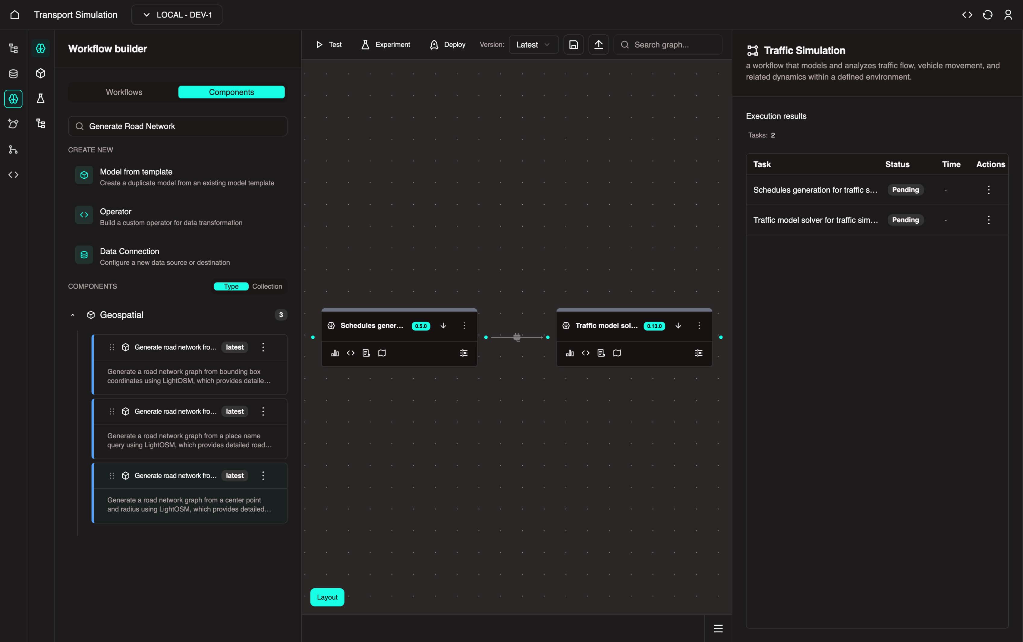
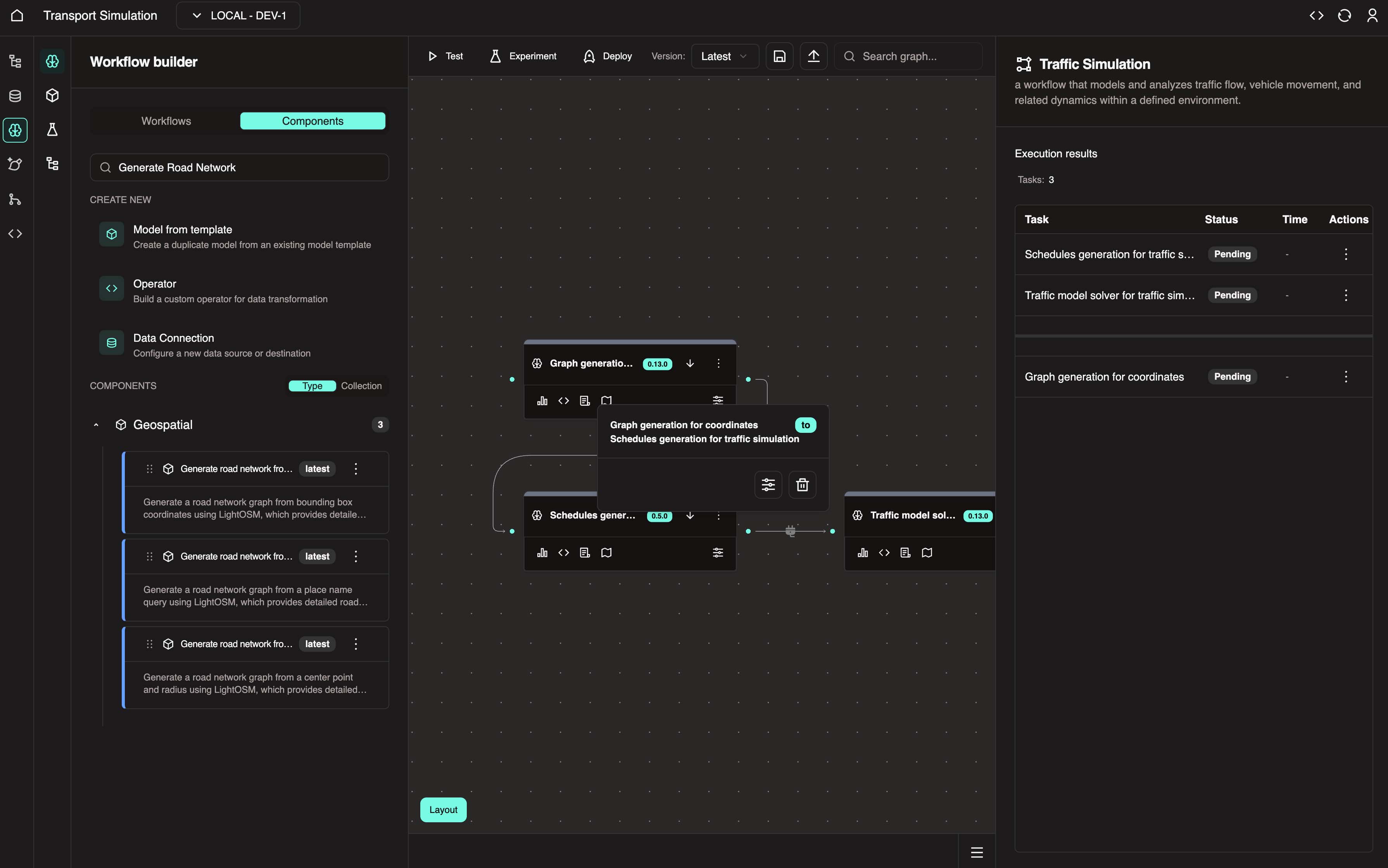
- Drag the right end of the Geospatial - Mapping node to the left end of the Schedule generation node to create a workflow dependency.
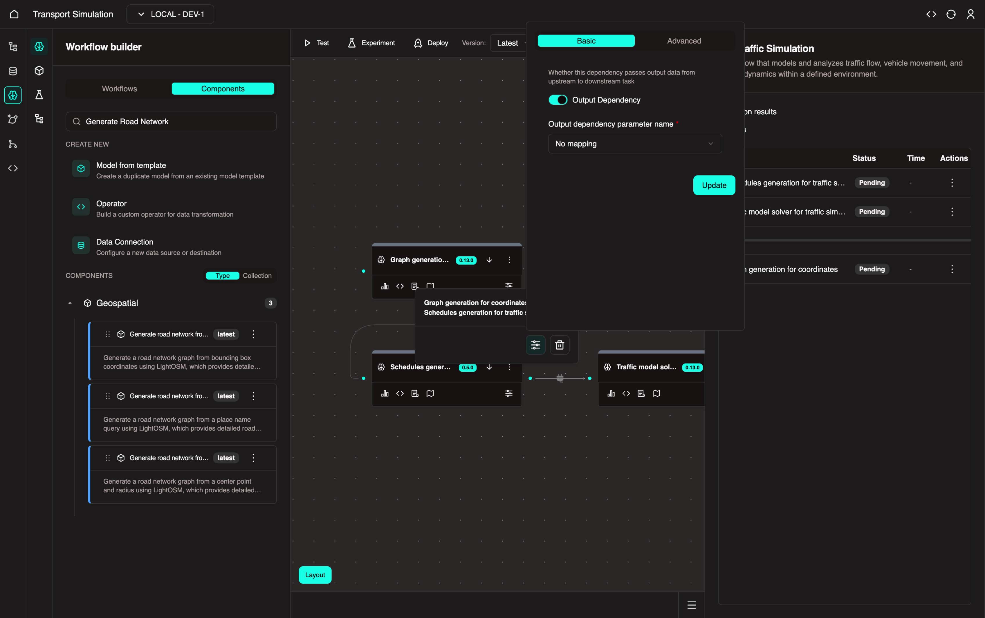
- To view or configure a connection between nodes, hover over the line connecting them to reveal the connection options.
- Click the Configure Connection icon, toggle Output Dependency, and click Update.
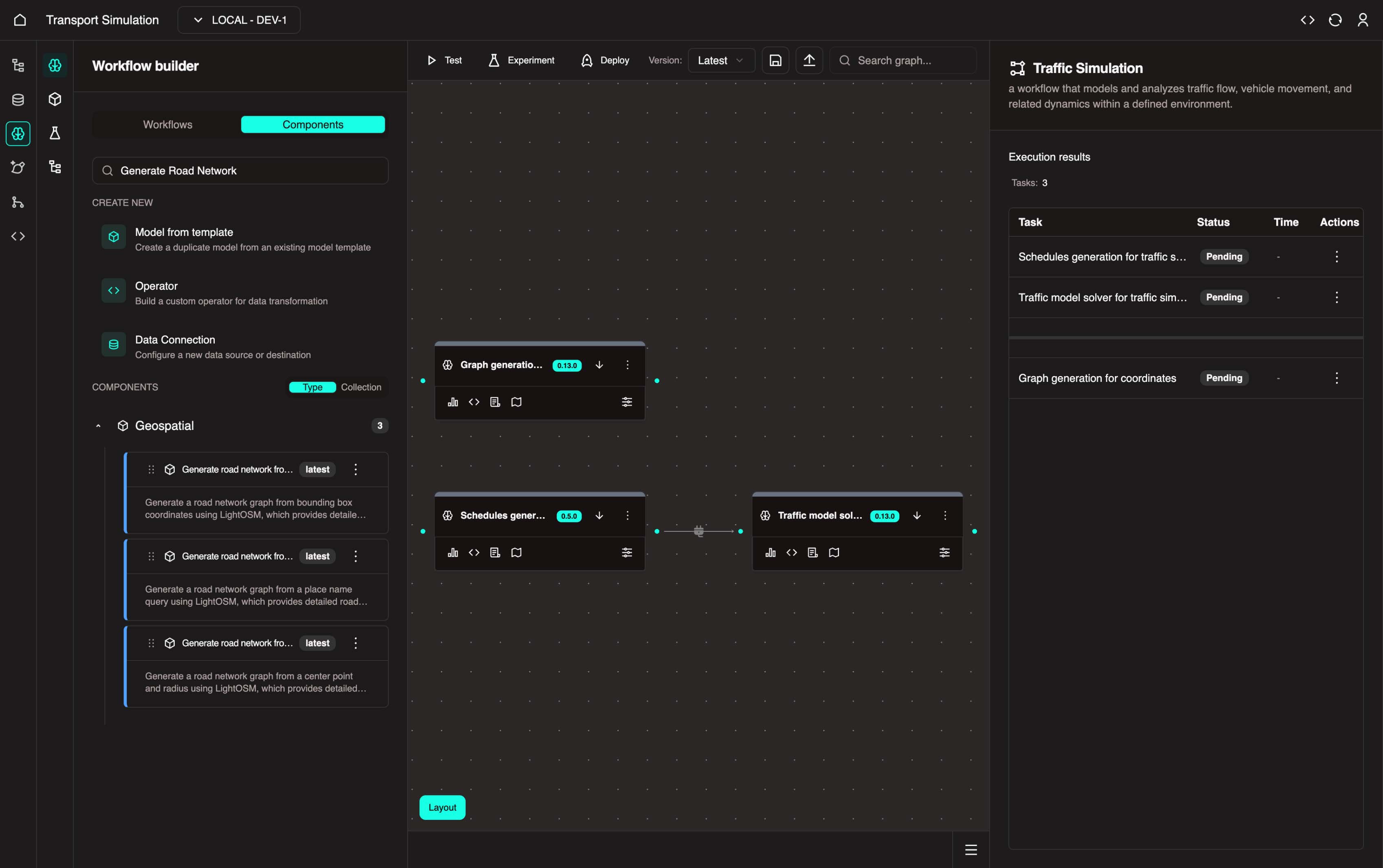
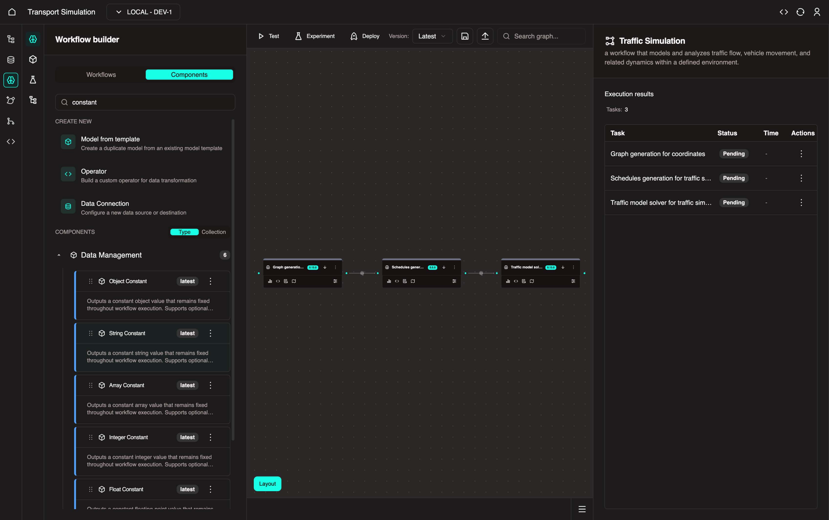
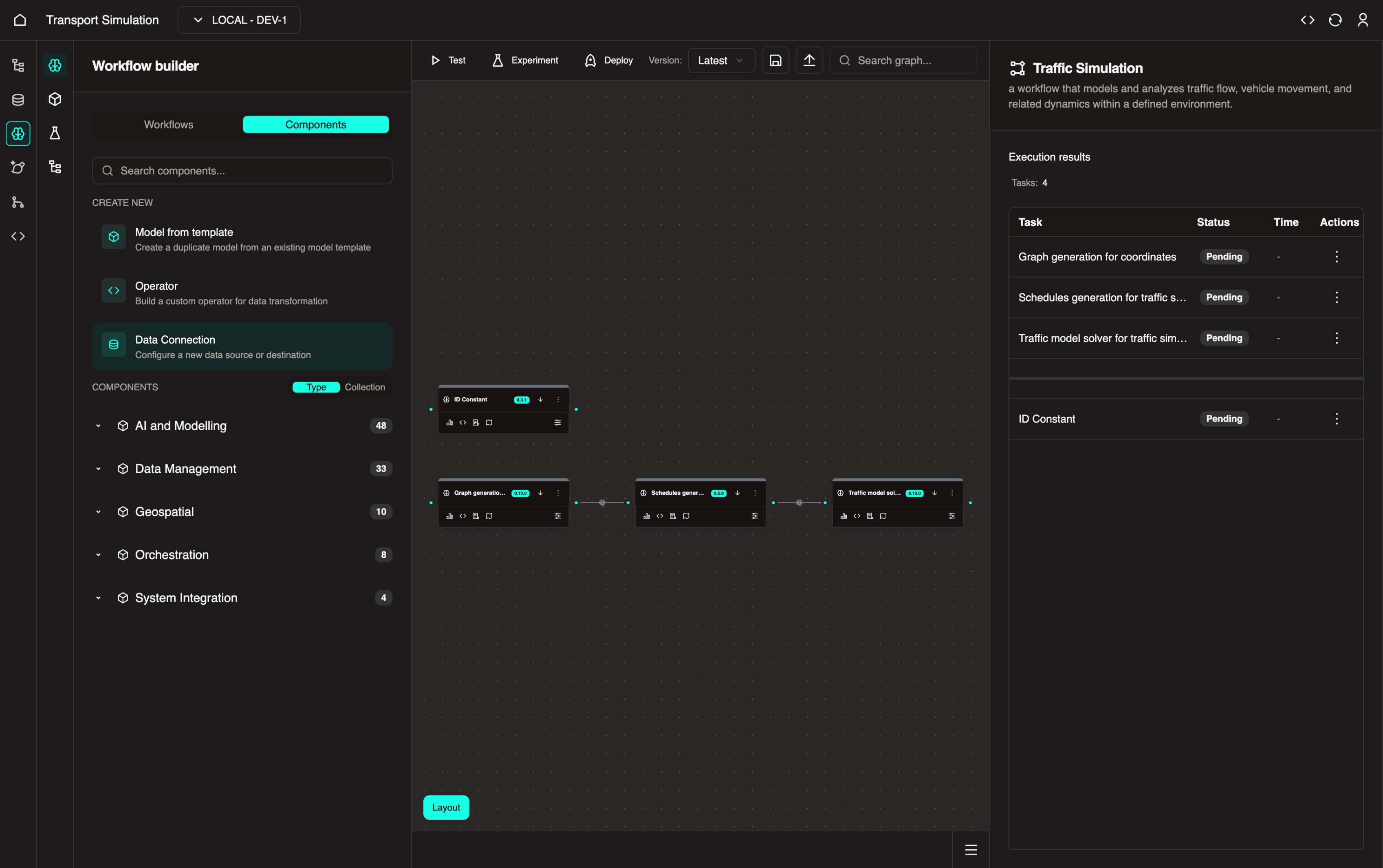
Your updated workflow should look like this:
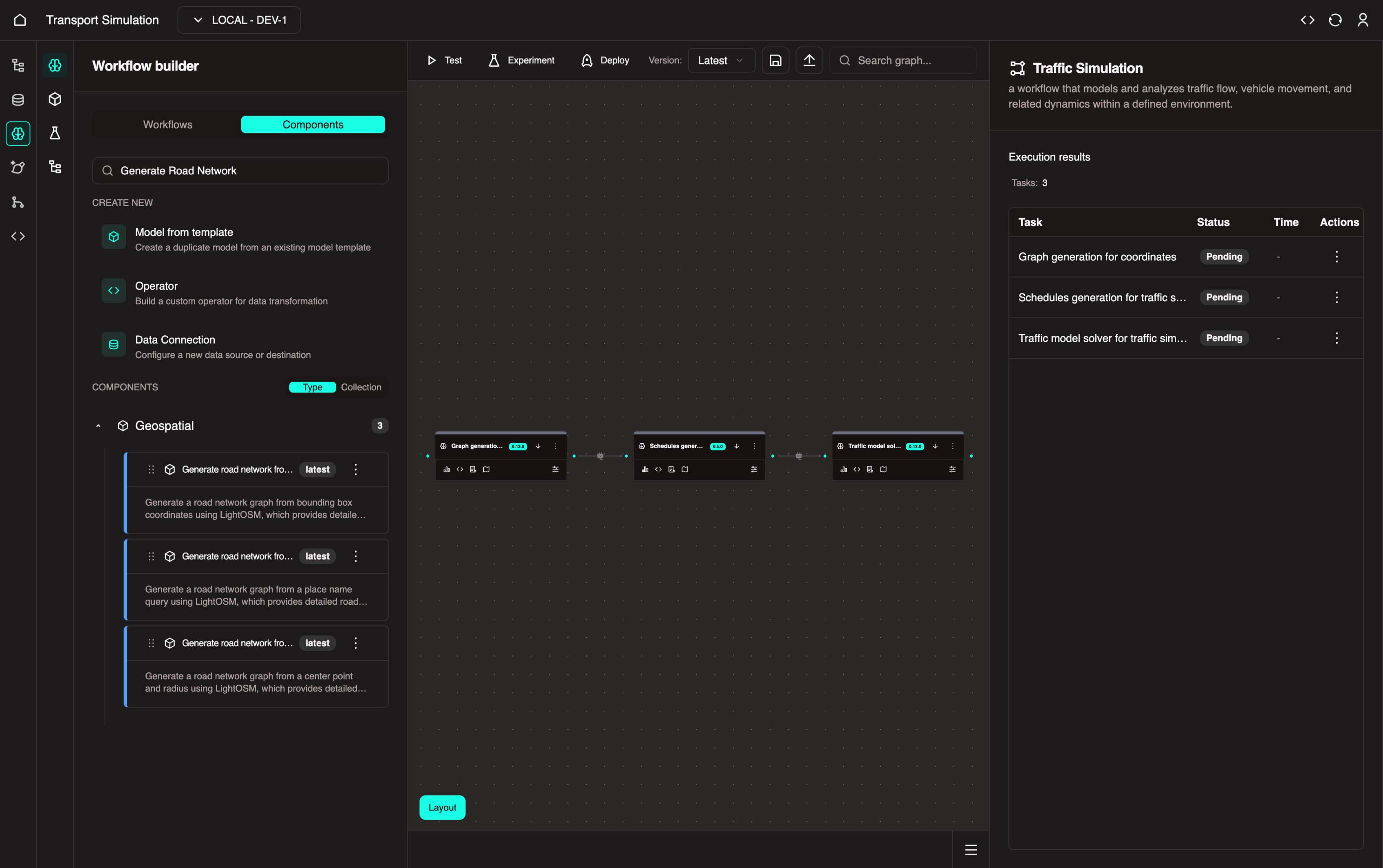
Understanding the Workflow
This workflow has three nodes:
Geospatial - Mapping: Uses
longitude,latitude, andradiusinputs to generate a map graph of roads and segments within the specified area. This sets the simulation location.Schedules generate for traffic simulation: Generates a random schedule of movements for
nvehicles/agents, placing them at the simulation location.Traffic model solver in traffic simulation: Uses all gathered information to simulate vehicle movements based on parameters like driver reaction speed, maximum speed, and minimum speed.
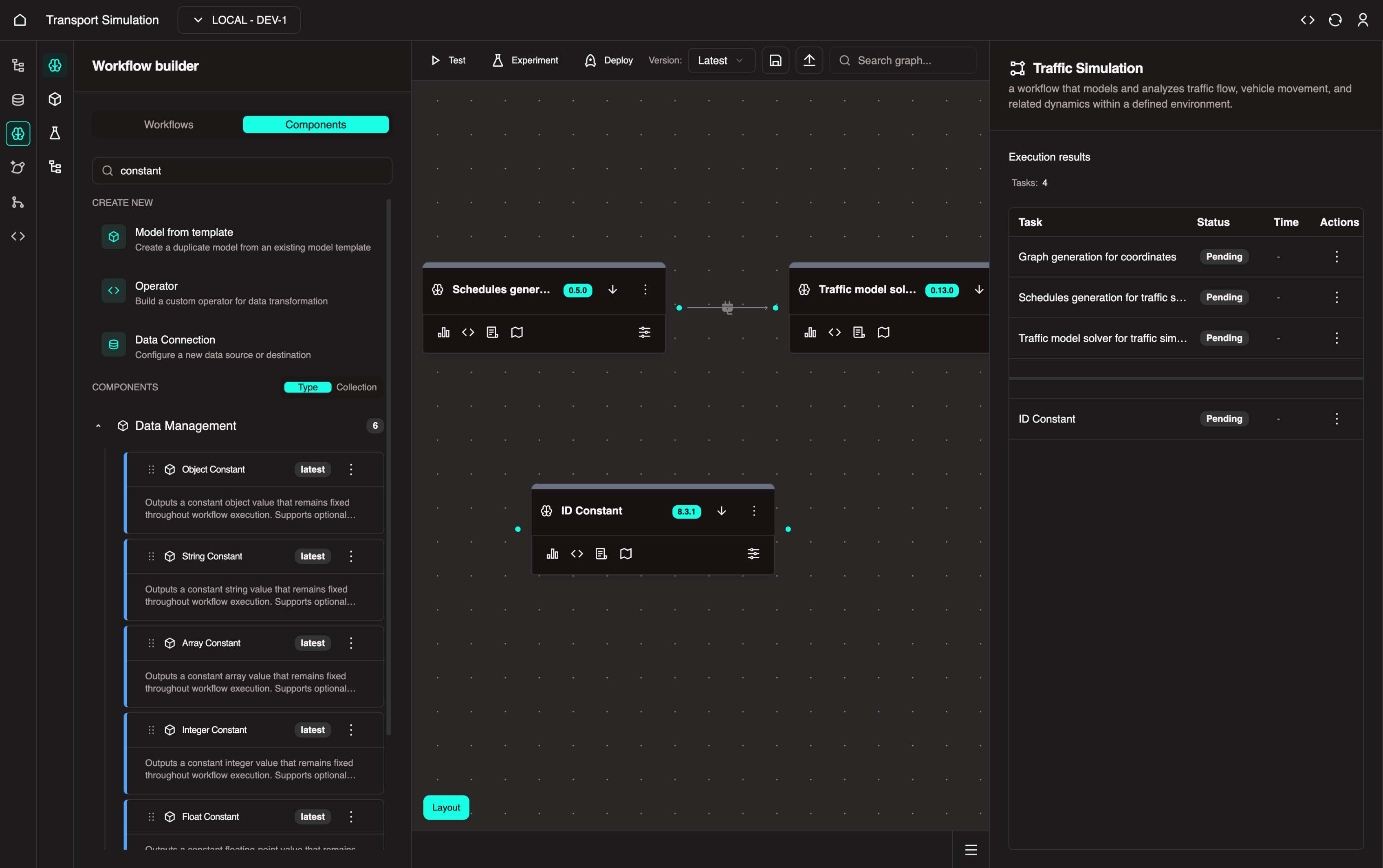
Adding a String Constant
- In the Components tab, search for constant.
- Click the Data Management collection
- Drag String Constant into the visualiser
Setting Default Inputs
- Click the Configure icon on the Geospatial - Mapping node to open its settings.
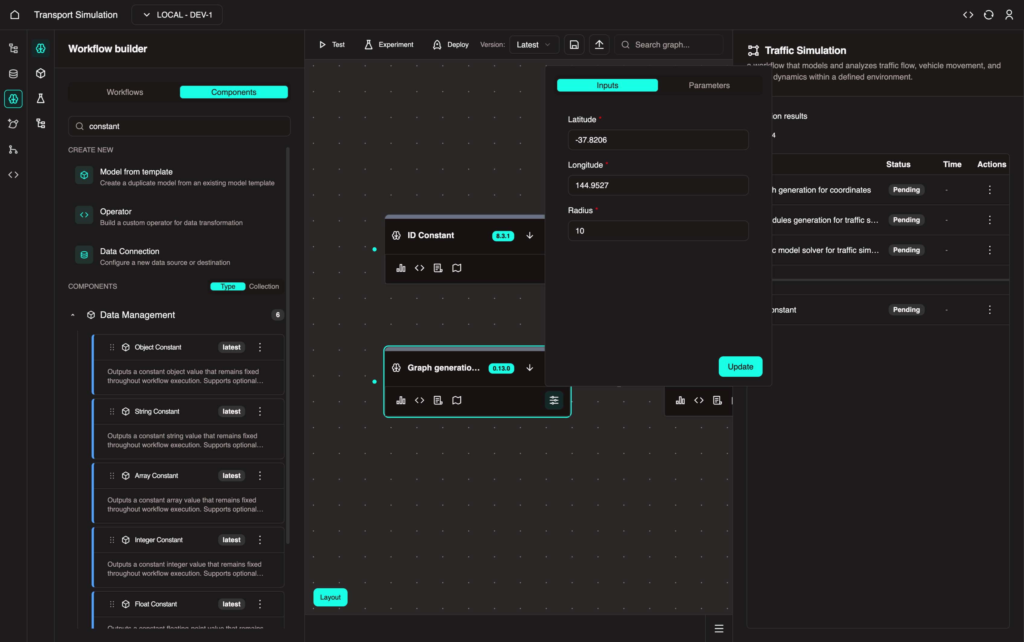
Here you can define longitude/latitude coordinates and the area radius. By default, this node generates a graph of Melbourne with a 10km radius.
You can update these coordinates or keep the defaults. Click Update when finished.
Click the Configure icon on the Schedules Generation for Traffic Simulation node. In the Parameters tab, update the
n_objectsvalue.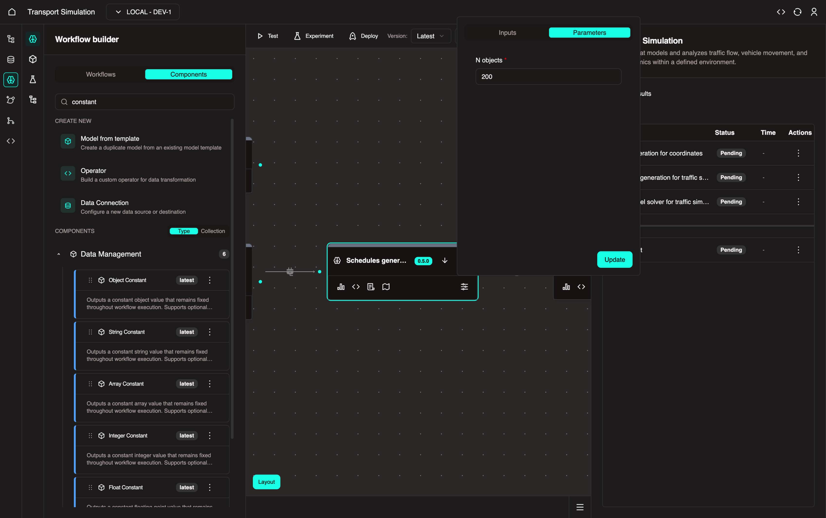
This controls the number of vehicles in the simulation. The default is 10. Set n_objects to 200 and click Update.
- Click the Configure icon on the Traffic Model Solver for Traffic Simulation node. In the Parameters tab, configure the simulation parameters:
For now, set start_time and end_time to span a 5-minute period. These values use Unix timestamps (Unix Timestamp Converter).
Time Constraints
end_timemust be greater thanstart_timedt(time step in seconds) must be greater than 0 and less than the time range
Recommended values:
- start_time =
1756795500 - end_time =
1756795800 - dt =
1
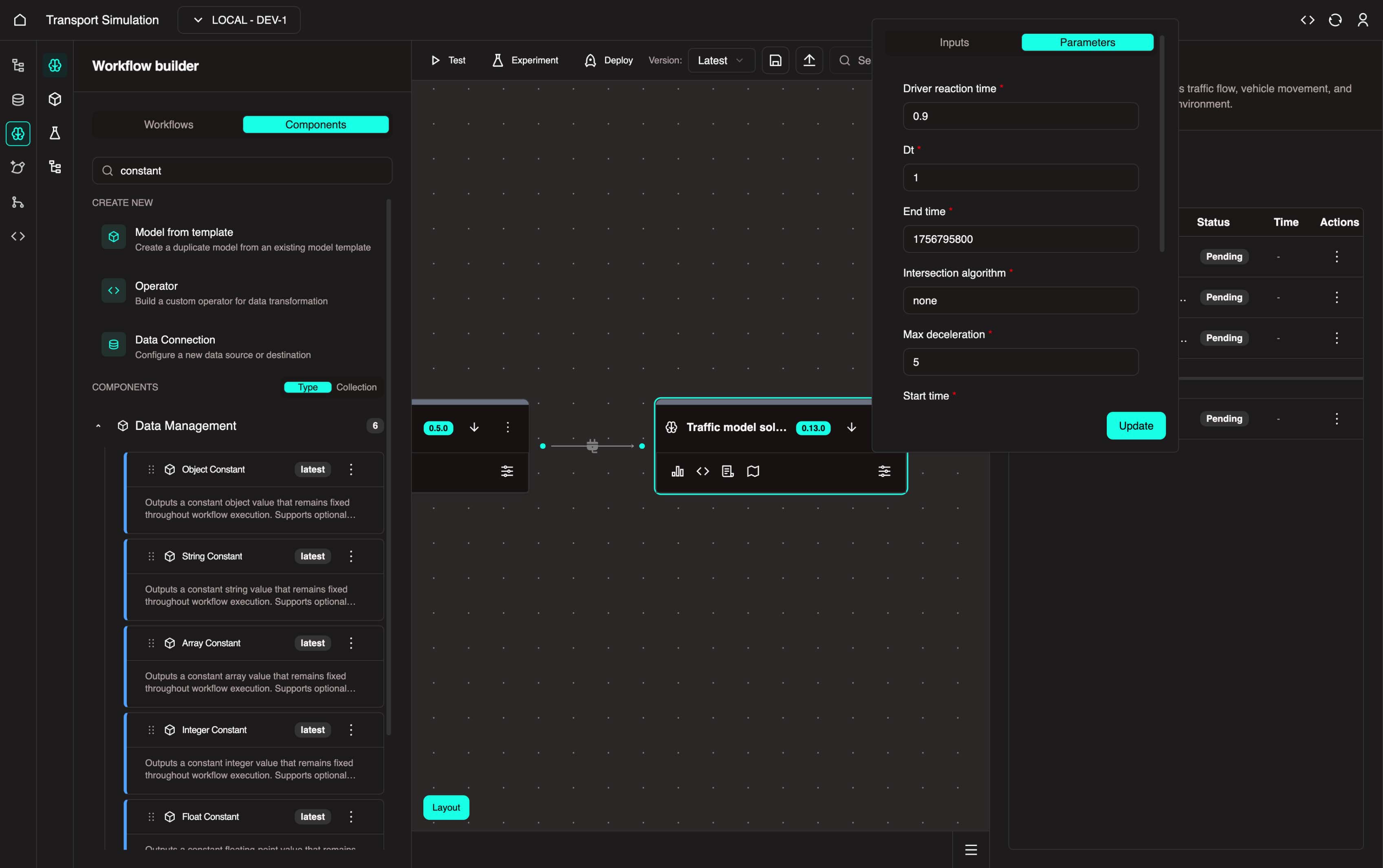
Click Update.
3.2 Creating Data Connections
Next, create a data connection to link the MDK workflow with your DDK schema.
What is a Data Connection?
A data connection bridges the DDK and MDK. In this example, it exports simulation results to your database table. Every time the simulation runs, the results are recorded.
When building a data connection, ensure the workflow aligns with the object/table you defined in the DDK.
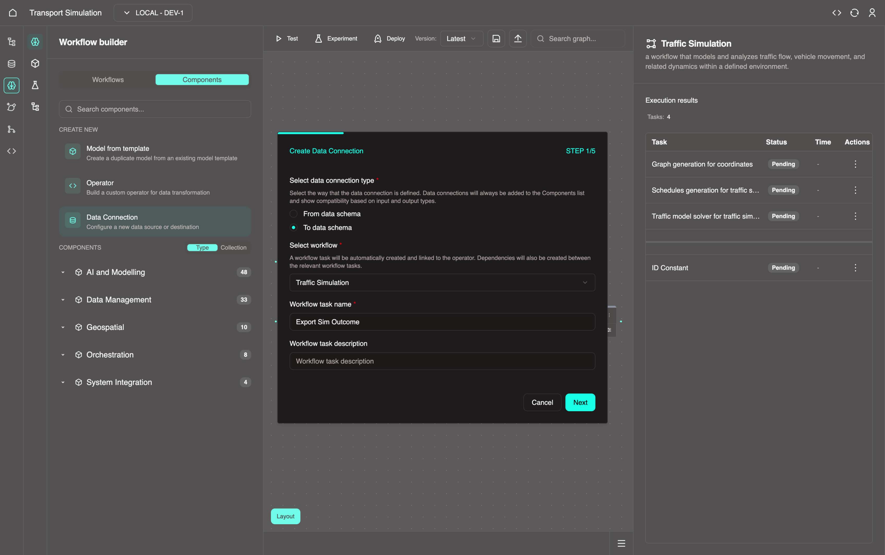
- Go to the Components tab. In the Create New section, click Data Connection to open the wizard.
Step 1/5: Task Details
- Configure the following:
- Select data connection type: Choose To data schema (other option: From data schema)
- Select workflow: Traffic Simulation
- Workflow task name:
Export Sim Outcome - Click Next
Step 2/5: Inputs and Outputs
- Configure the task inputs and outputs:
- Preceding workflow tasks: Select Traffic model solver for traffic simulation
- Data connection input key: Enter
solver - Click +Add preceding task and select Data Management - Constants
- Enter
stringconstantas the input key - Following object: Select
SimOutcome - Object resolver: Select
createSimOutcome - Click Next
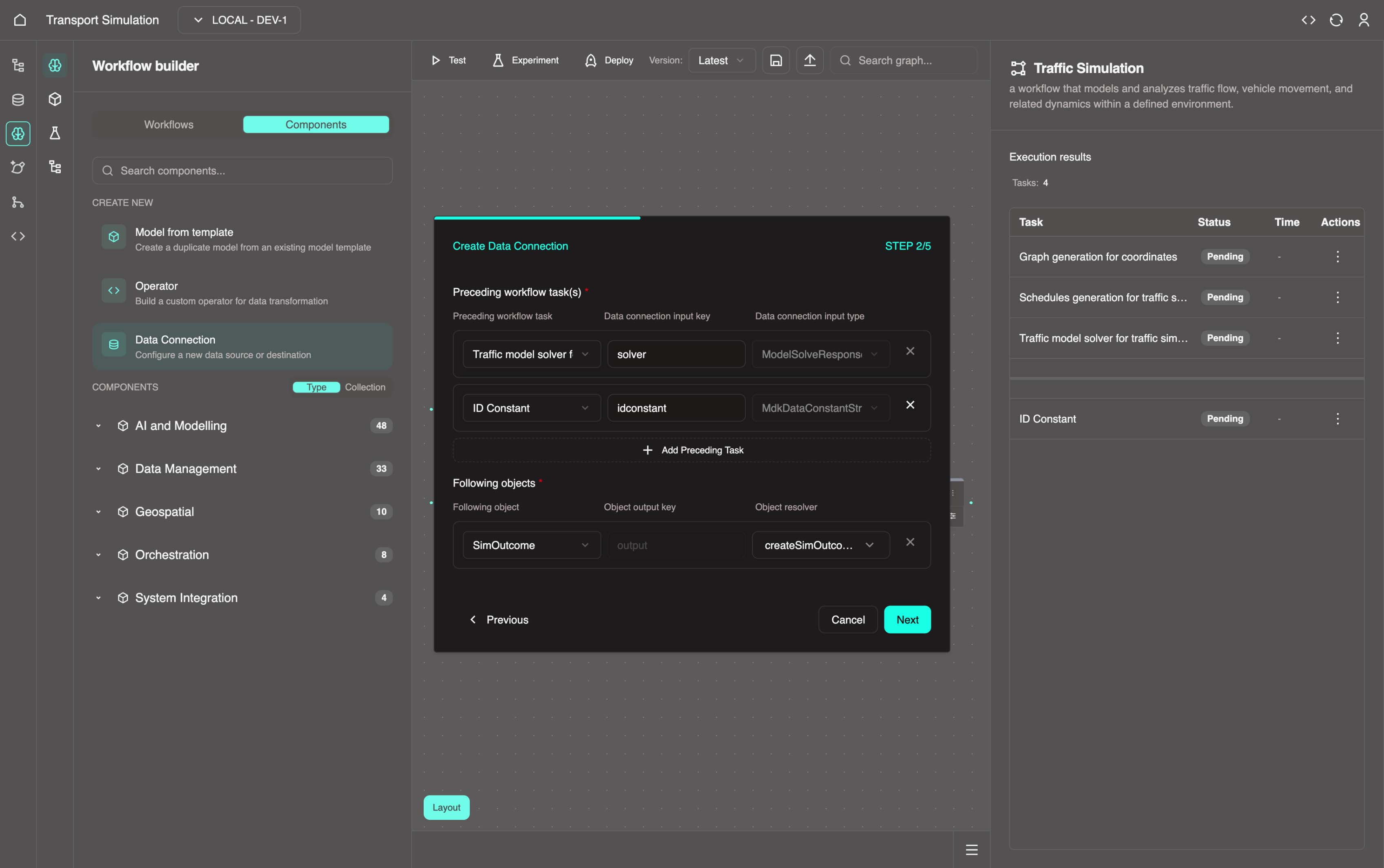
INFO
This step defines the inputs and outputs of the data connection task. Simulation results are exported to the SimOutcome object via the createSimOutcome resolver, adding a new row to the database.
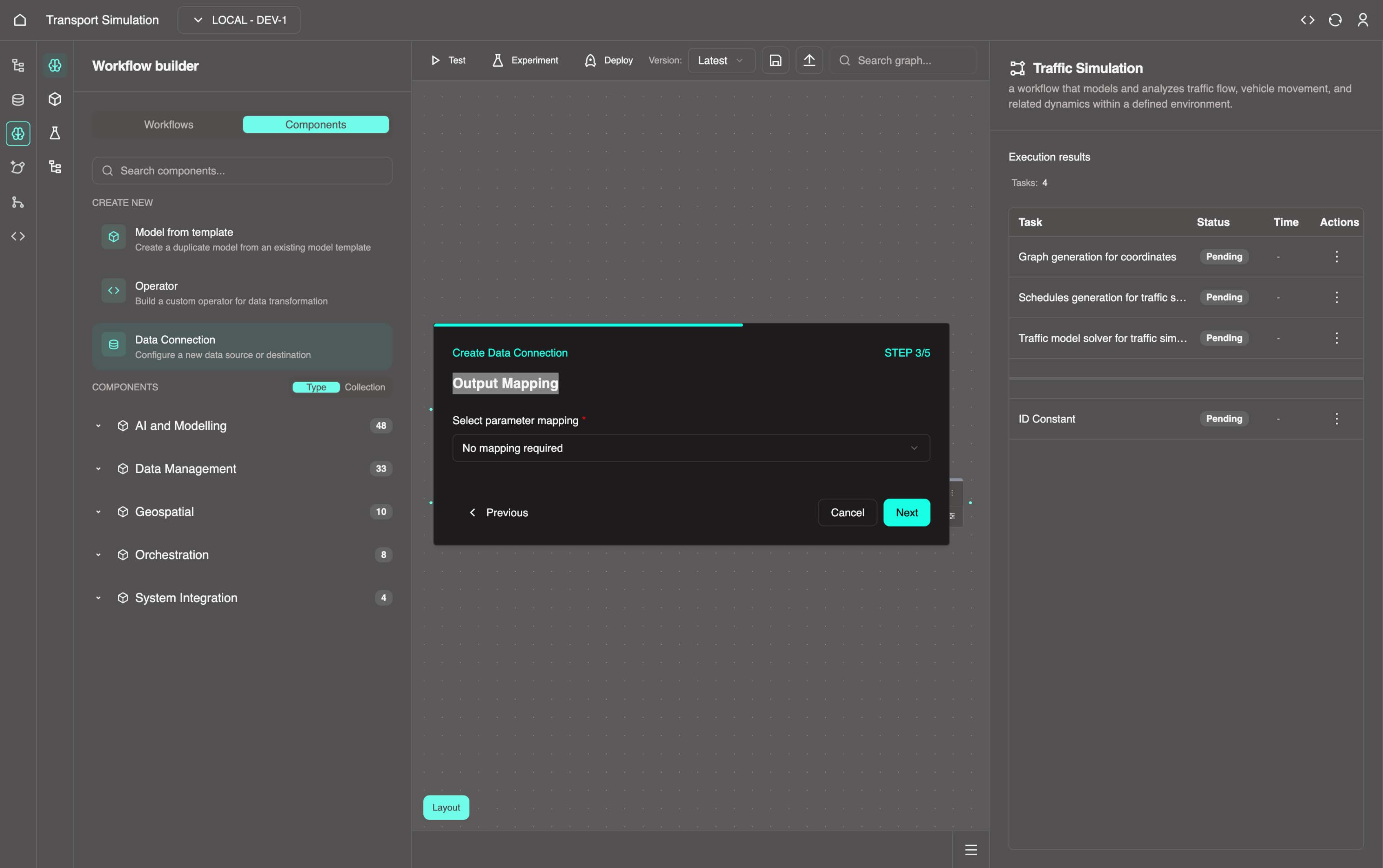
Step 3/5: Output Mapping
- No changes required. Click Next.
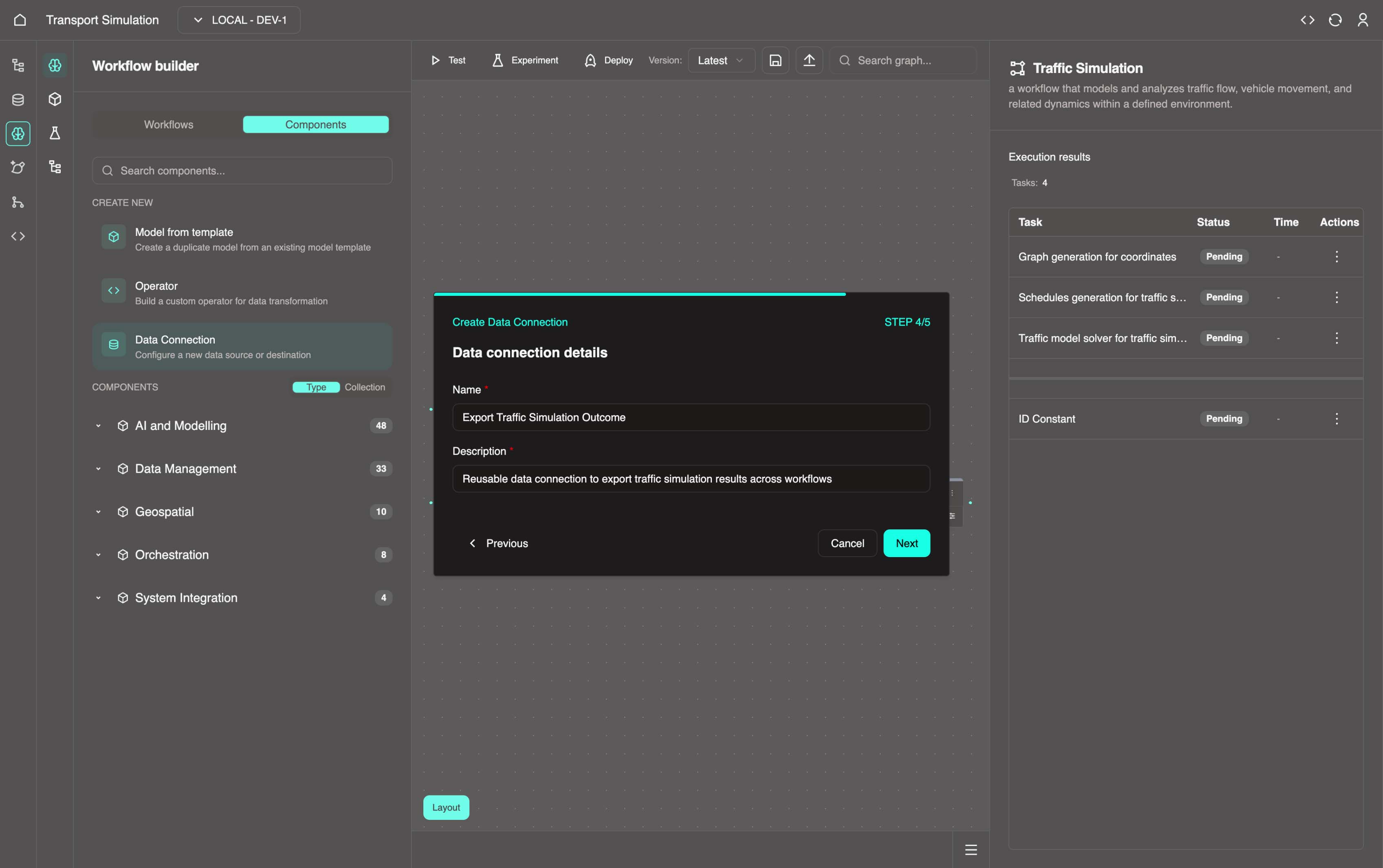
Step 4/5: Data Connection Details
- Configure the data connection:
- Name:
Export Traffic Simulation Outcome - Description: Add a brief description (required)
- Name:
INFO
This creates a reusable node called Export Traffic Simulation Outcome in the MDK. This is useful for reusing the same data connection across other simulation workflows.
Step 5/5: Configuration
- In the Operator code field, copy and paste the code below, then click Create.
python
class ExportTrafficSimulationOutcomeParams(BaseModel):
    """
        Implementation parameters structure
    """
    param_1: str = "default"


class TrafficModelGeoJSONTrip(BaseModel):
    """
    Implementation input data structure
    """
    data: dict
    type: str = "Timeseries"


    def __repr__(self):
        return json.dumps(self.model_dump())


class ModelSolveResponse(BaseModel):
    """
    Implementation input data structure
    """
    geo_json_trip: TrafficModelGeoJSONTrip


    def __repr__(self):
        return json.dumps(self.model_dump())


class DataConstantResponse(BaseModel):
    """
    Implementation input data structure
    """
    value: str = "example string"


    def __repr__(self):
        return json.dumps(self.model_dump())


class CreateSimOutcome(BaseModel):
    """
    Internal response data as a struct
    """
    id: str
    dtTimestamp: int
    result: str
    simSettingsId: str


    def __repr__(self):
        return json.dumps(self.model_dump())


TrafficModelGeoJSONTrip.model_rebuild()
ModelSolveResponse.model_rebuild()
DataConstantResponse.model_rebuild()
CreateSimOutcome.model_rebuild()

"""
- Please make sure to access the input key properly.
E.g.:
    input0 = solver.geo_json_trip
    input1 = stringconstant.value

- You must return an output of type `CreateSimOutcome` (example provided below).
"""


def export_traffic_simulation_outcome(solver: ModelSolveResponse, stringconstant: DataConstantResponse) -> CreateSimOutcome:
    return CreateSimOutcome(
        id=str(uuid.uuid4()),
        dtTimestamp=int(time.time()),
        result=solver.model_dump_json(),
        simSettingsId=stringconstant.value
    ) 	# Update output return type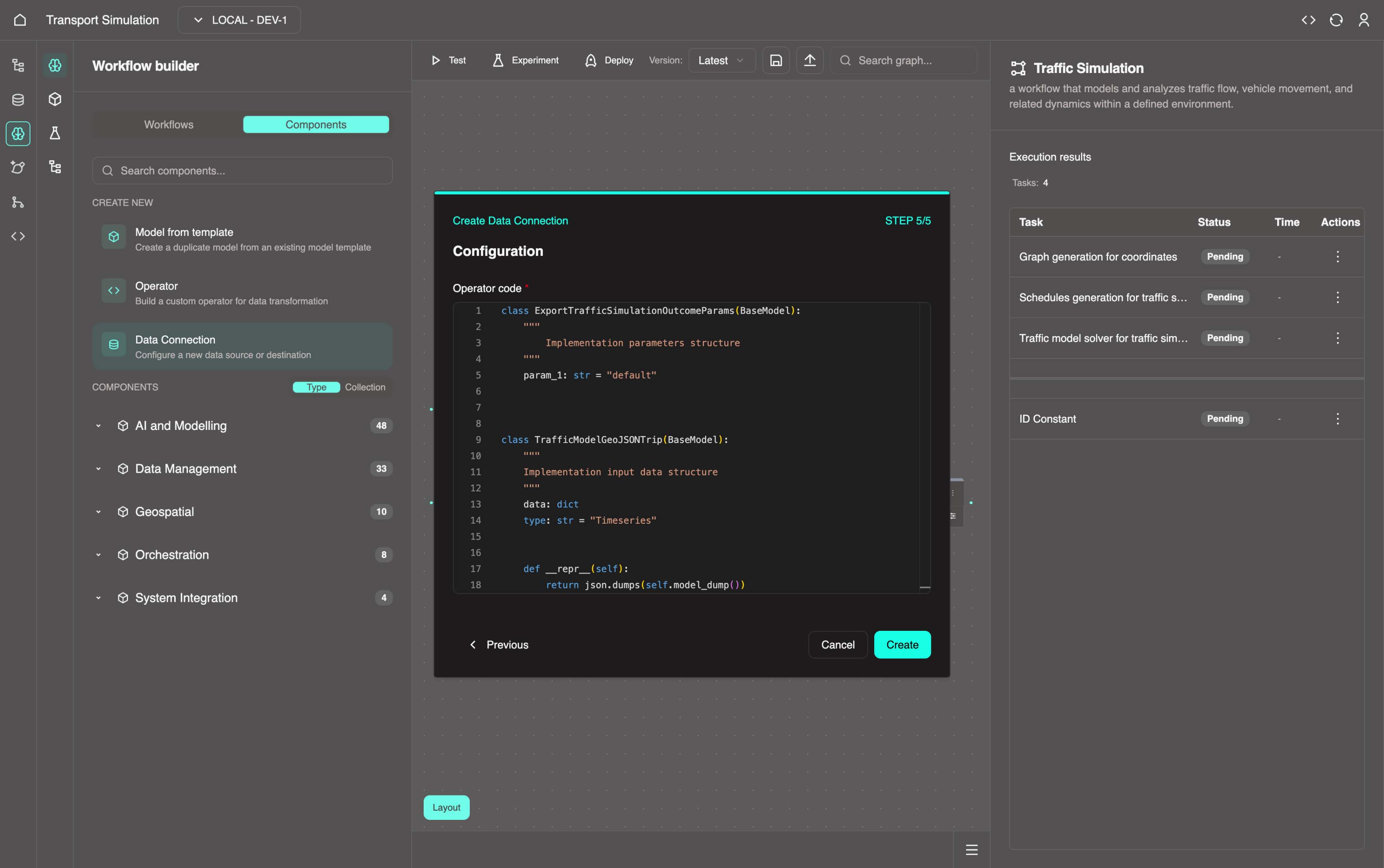
Understanding the Code
The top portion is auto-generated template code. The key part is the function definition on line 75:
python
def export_traffic_simulation_outcome(solver: ModelSolveResponse, stringconstant: DataConstantResponse) -> CreateSimOutcome:If your DDK schema has different field names than the CreateSimOutcome class, update the fields accordingly.
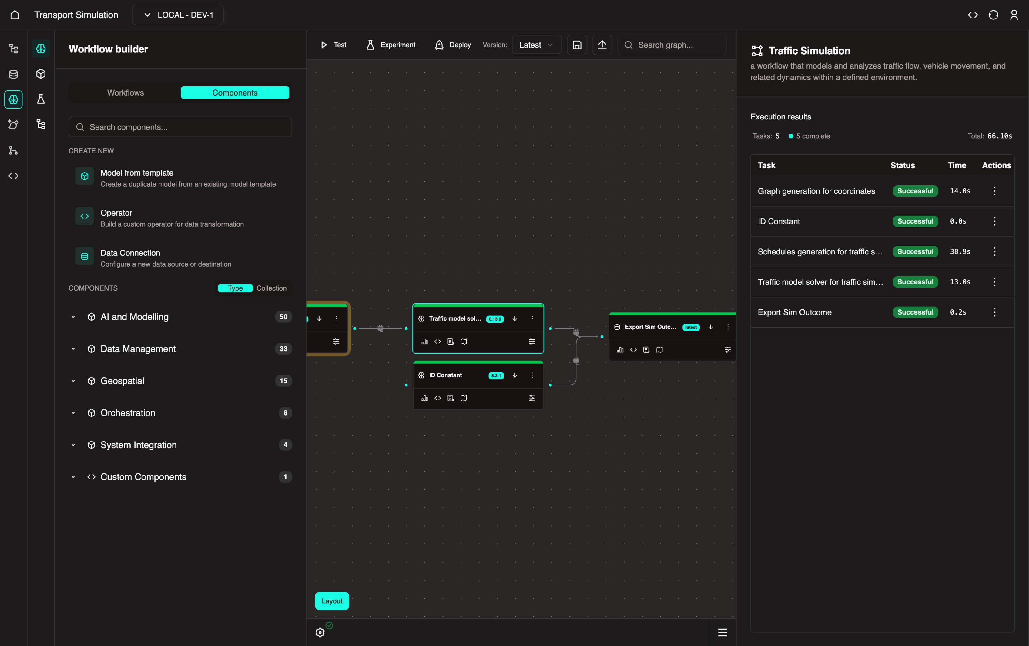
After creation, your workflow should look like this:
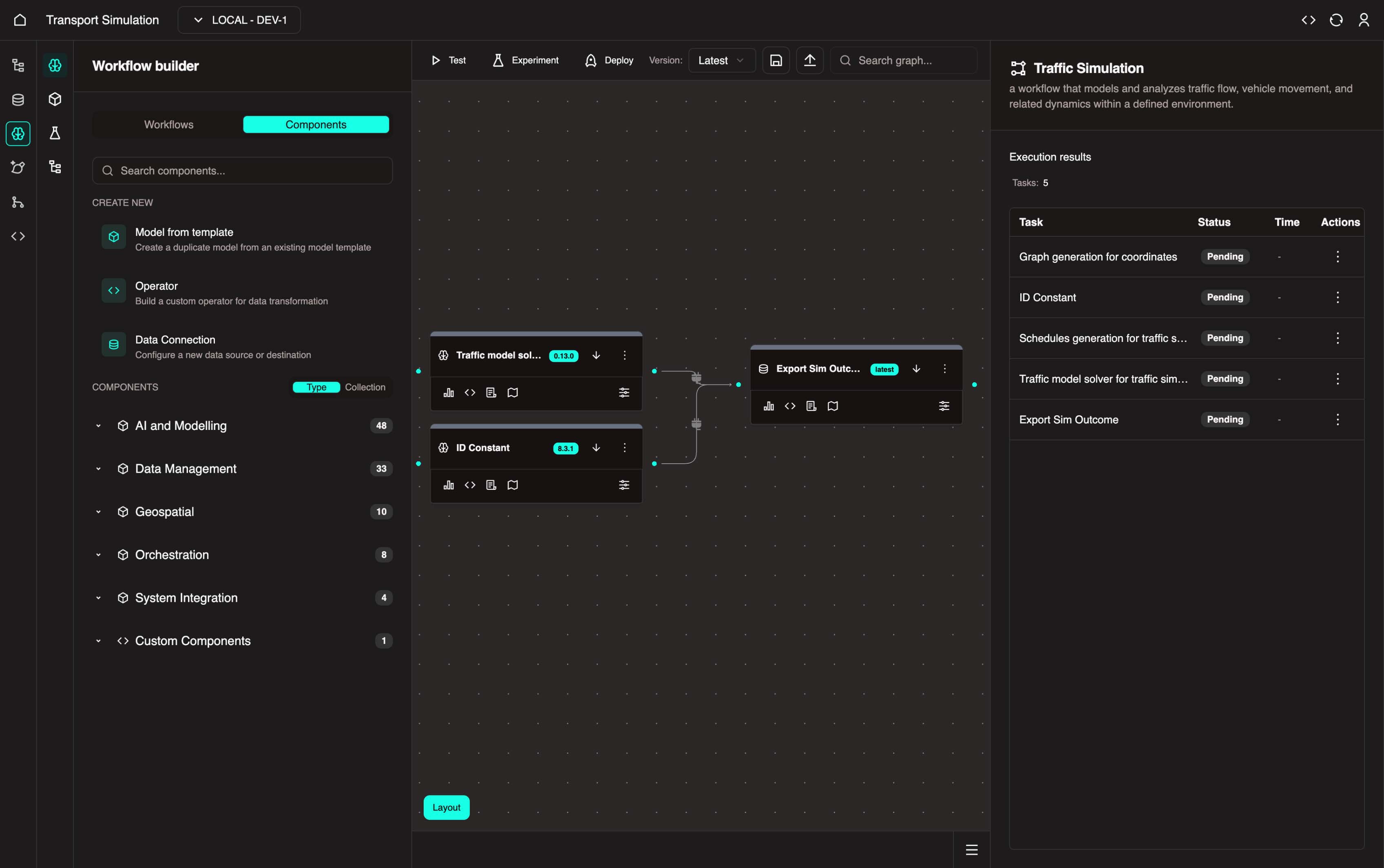
INFO
Your workflow now exports simulation results to the SimOutcome table. The Data Management - Constants node provides a unique ID for each row created when the simulation runs.
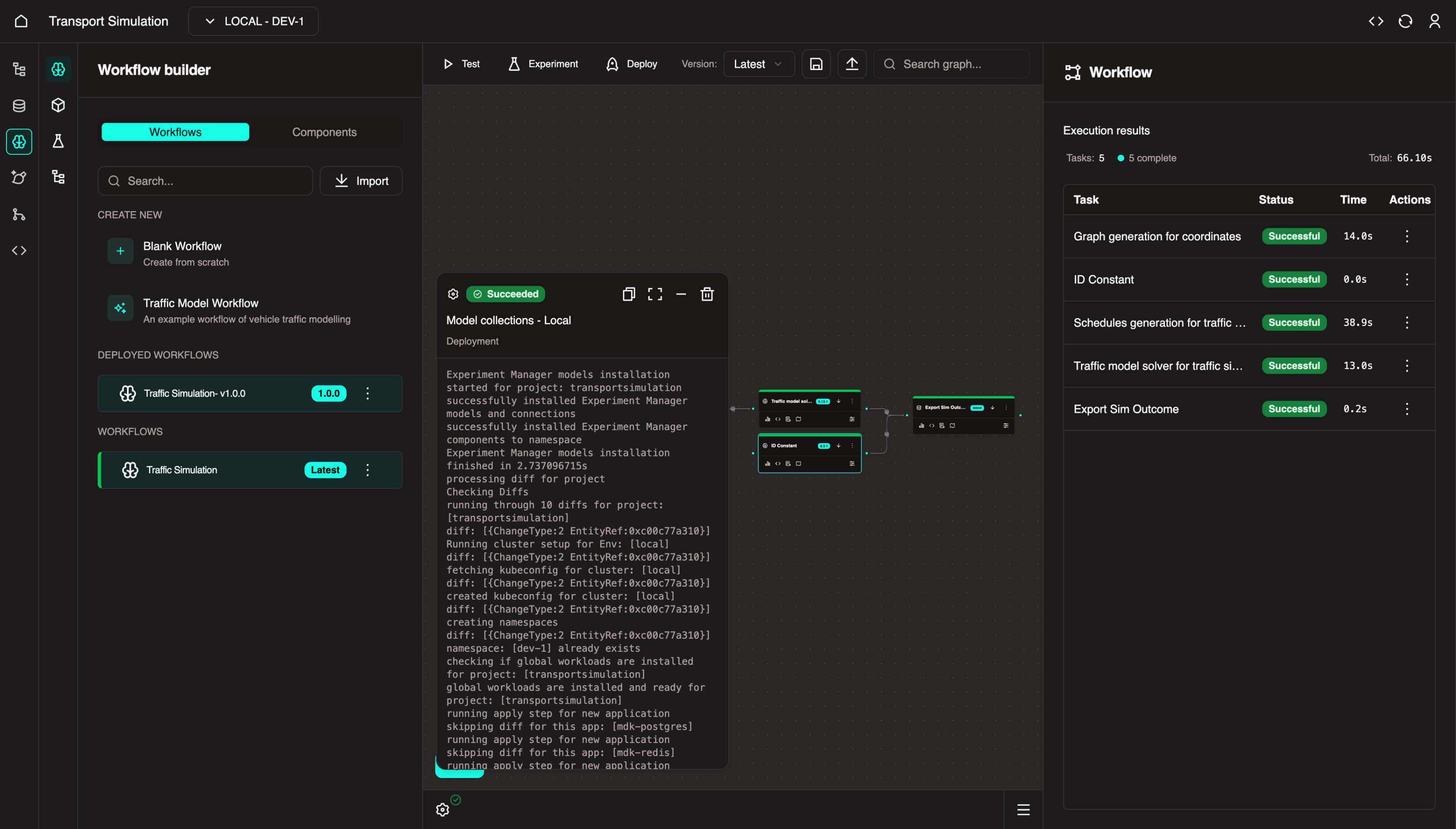
3.3 Testing Your Workflow
Use Test Execution to test and refine parameters before deployment.
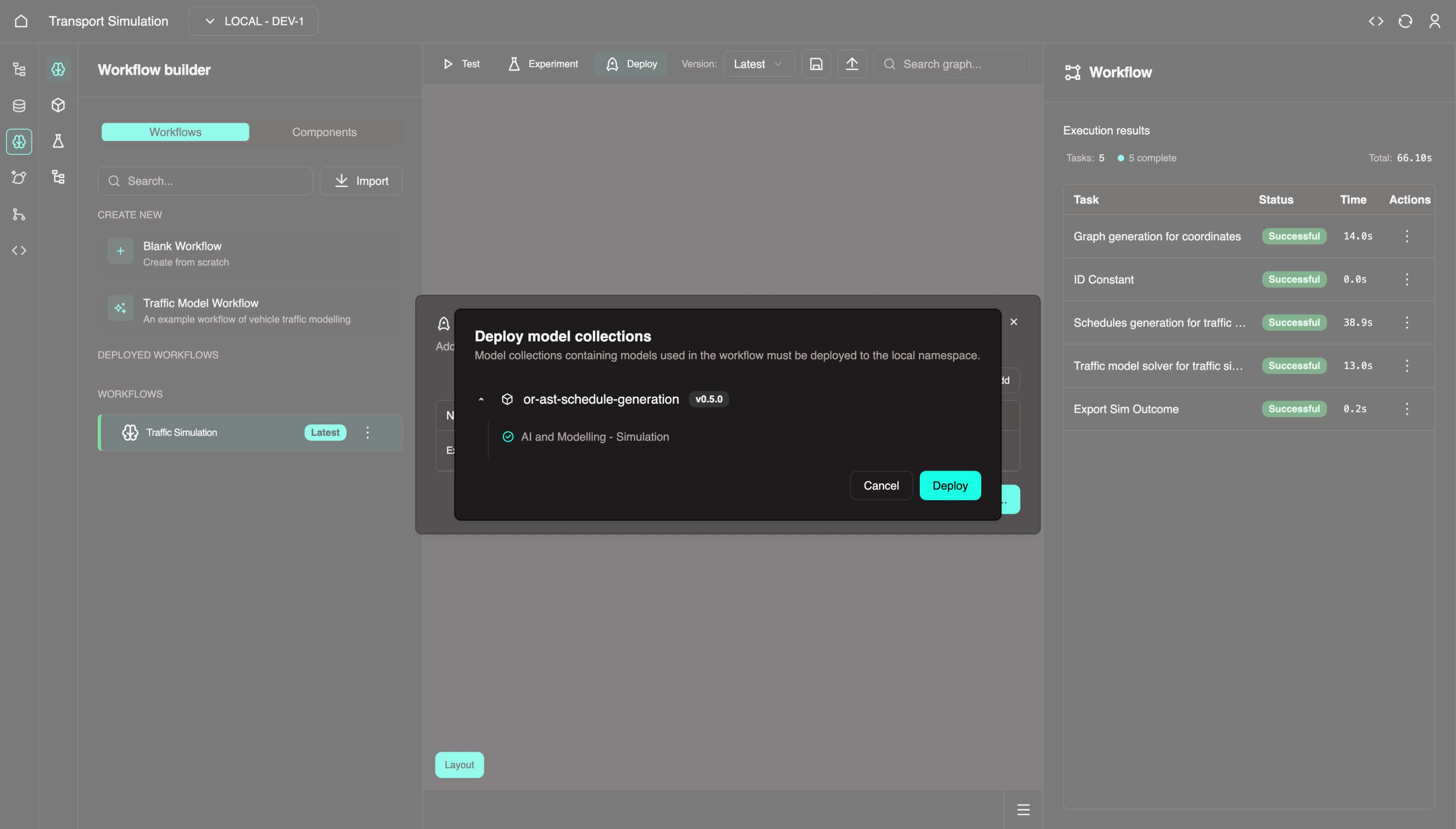
- Click the Test execute button (play icon) in the top center panel. This opens a Deploy model collections panel.
- Click Deploy. Once complete, the workflow executes to test for any issues.
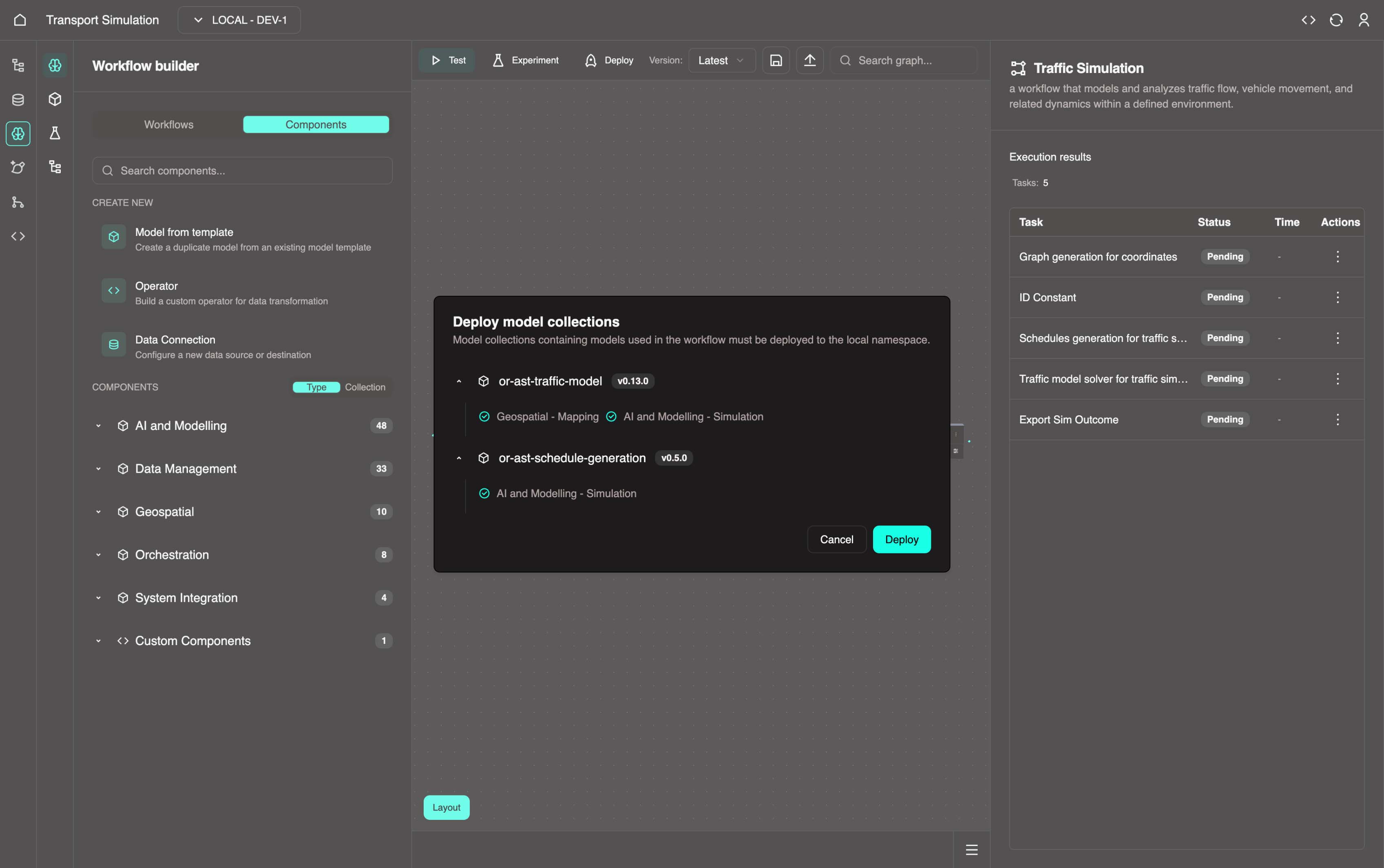
If successful, all nodes turn green.
TIP
The first execution often takes longer as services pre-compile.
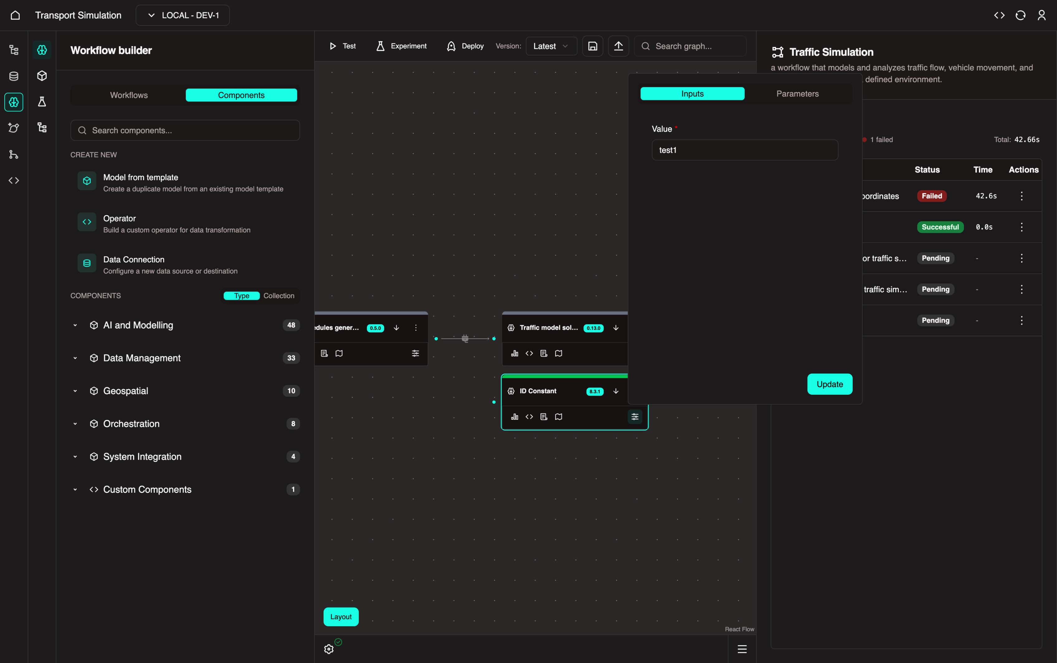
Troubleshooting
If the Data Export task fails, see the troubleshooting section below.
Fix for Failing Data Export Task
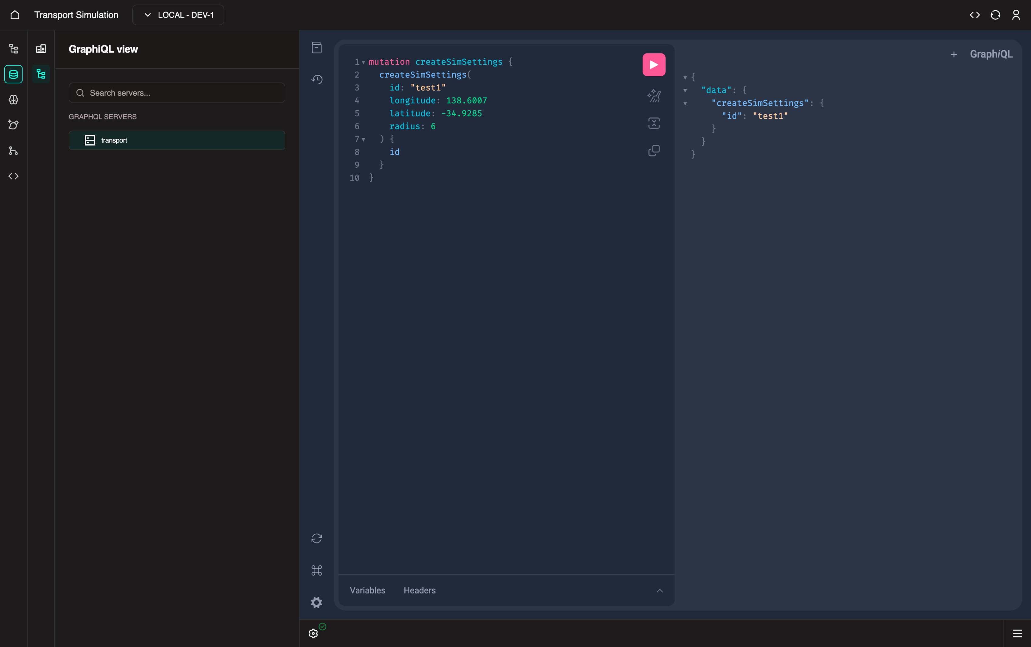
Navigate to the DDK and select the GraphiQL tab.
Access the
GraphiQLplayground with all schema resolvers. If you can't see the playground, contact the OR team.Paste and execute the code below to manually create a
SimSettingsobject with thetest1ID:
graphql
mutation createSimSettings {
  createSimSettings(
    id: "test1"
    longitude: 138.6007
    latitude: -34.9285
    radius: 6
  ) {
    id
  }
}
Return to MDK and select the Data Management - Constants node.
Set the input value to
test1and click Update.
- Run test execute again. All tasks should now succeed.
Model Version Requirements
If tests continue to fail, ensure you're using:
- Traffic Models: version 0.13.1
- Schedule Generation Models: version 0.5.1
To update a model, click the three dots on the model node and select Upgrade model configuration. Choose the required version and click Update.
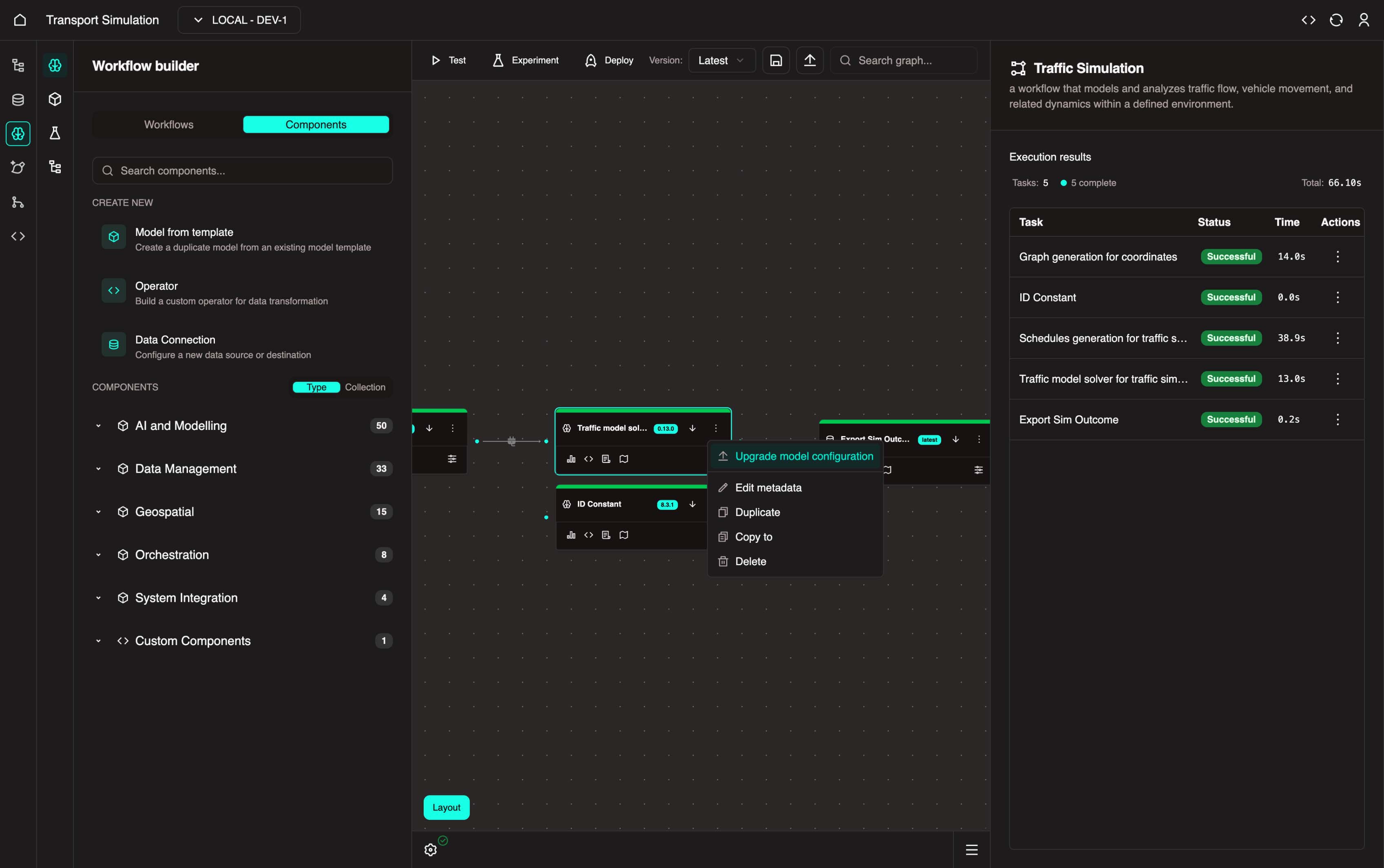
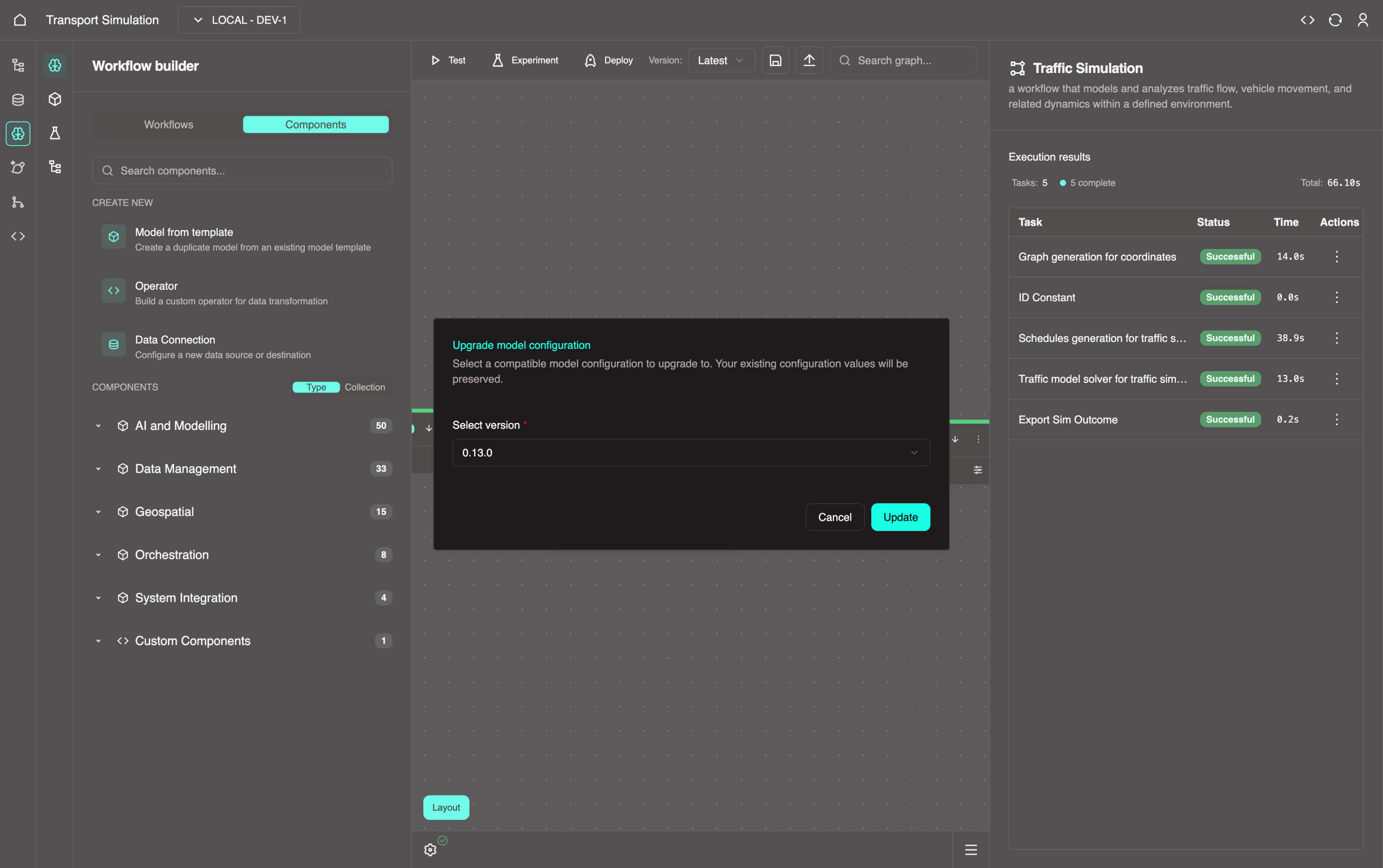
If issues persist after updating, contact OR Support.
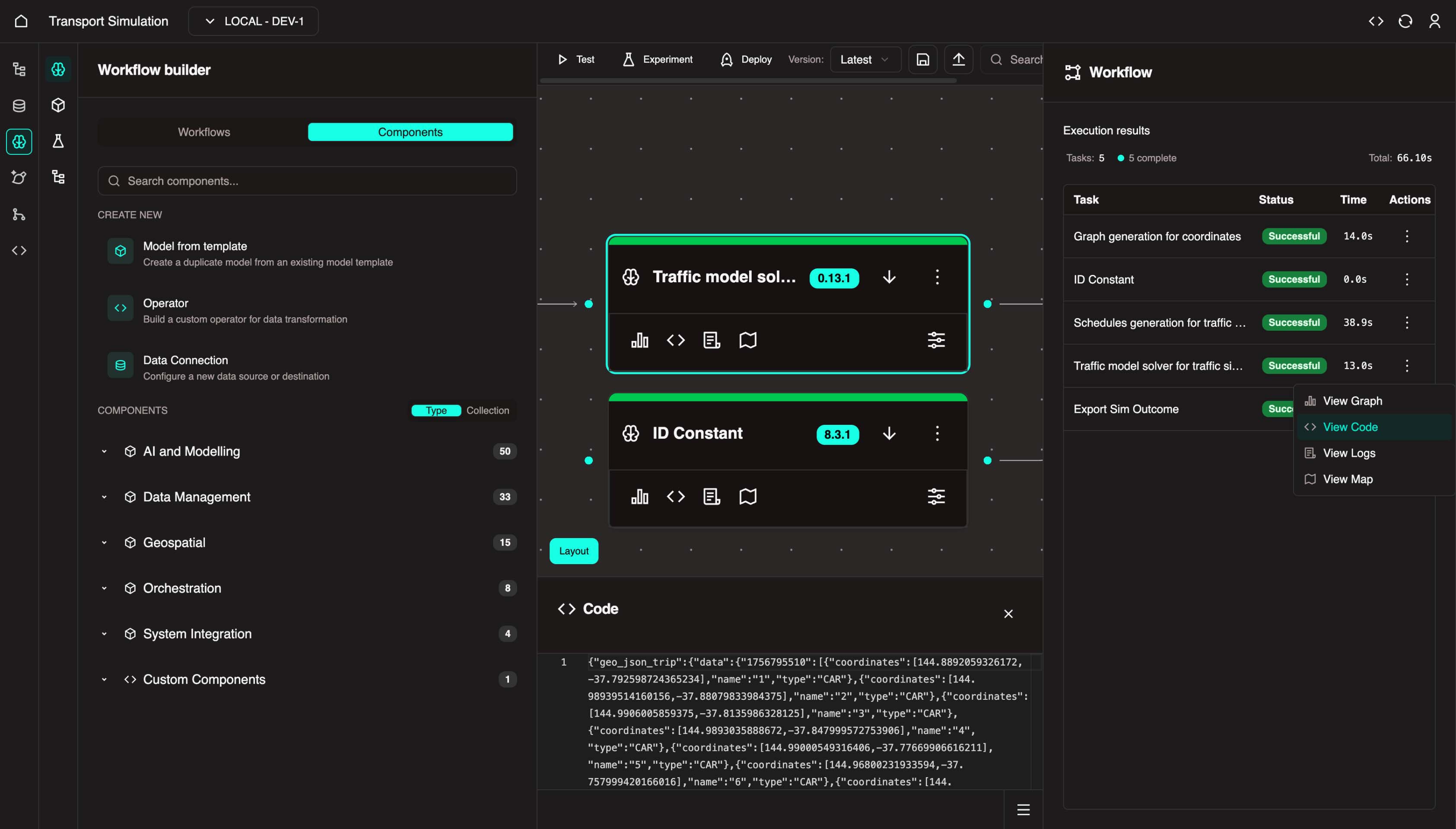
Viewing Results
- On the Traffic Model Solver node, click the View Code button (
</>) to see execution results in the bottom panel.
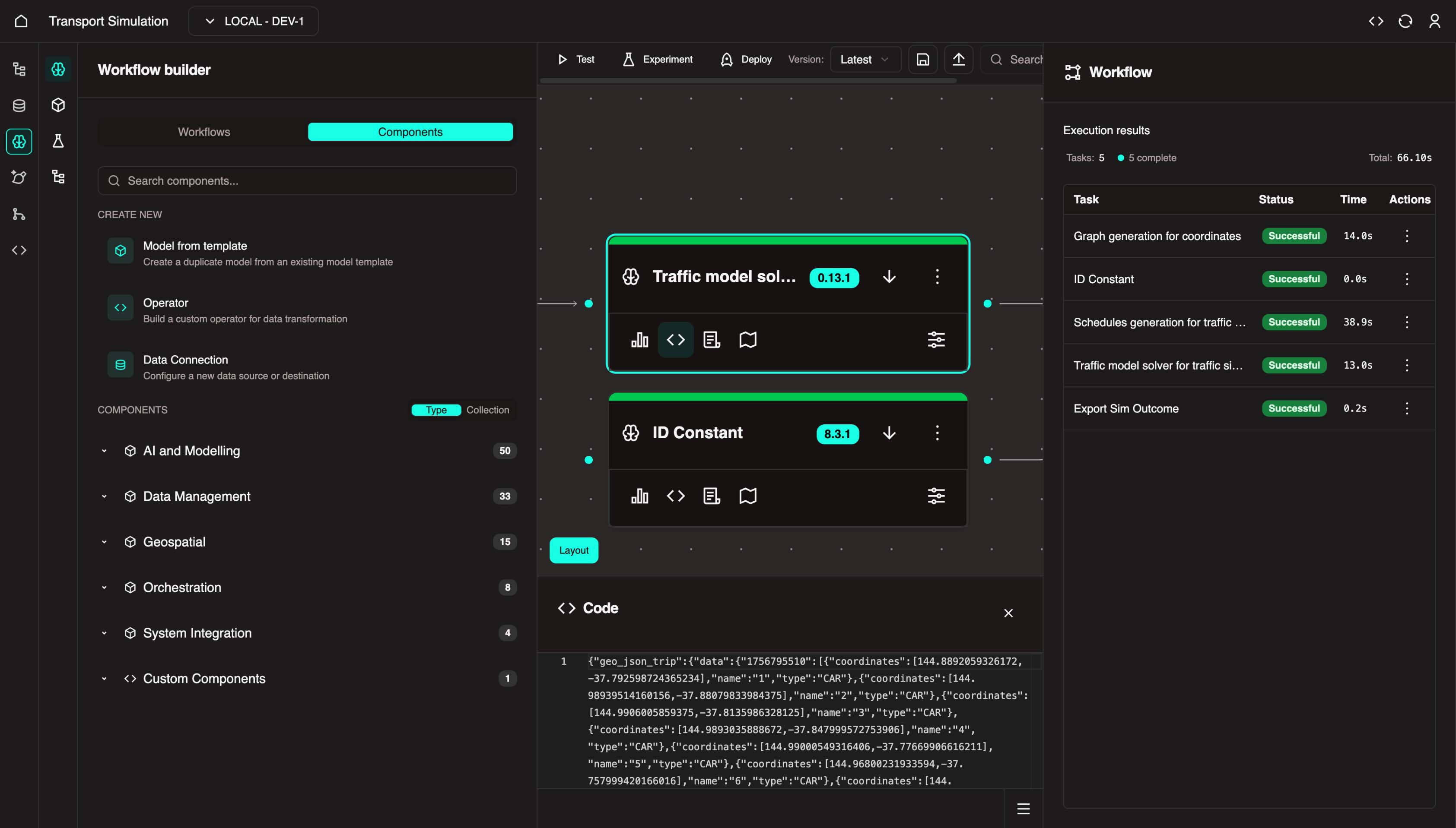
Alternative Access
You can also access task actions from the right panel by clicking the three dots and selecting the desired action.
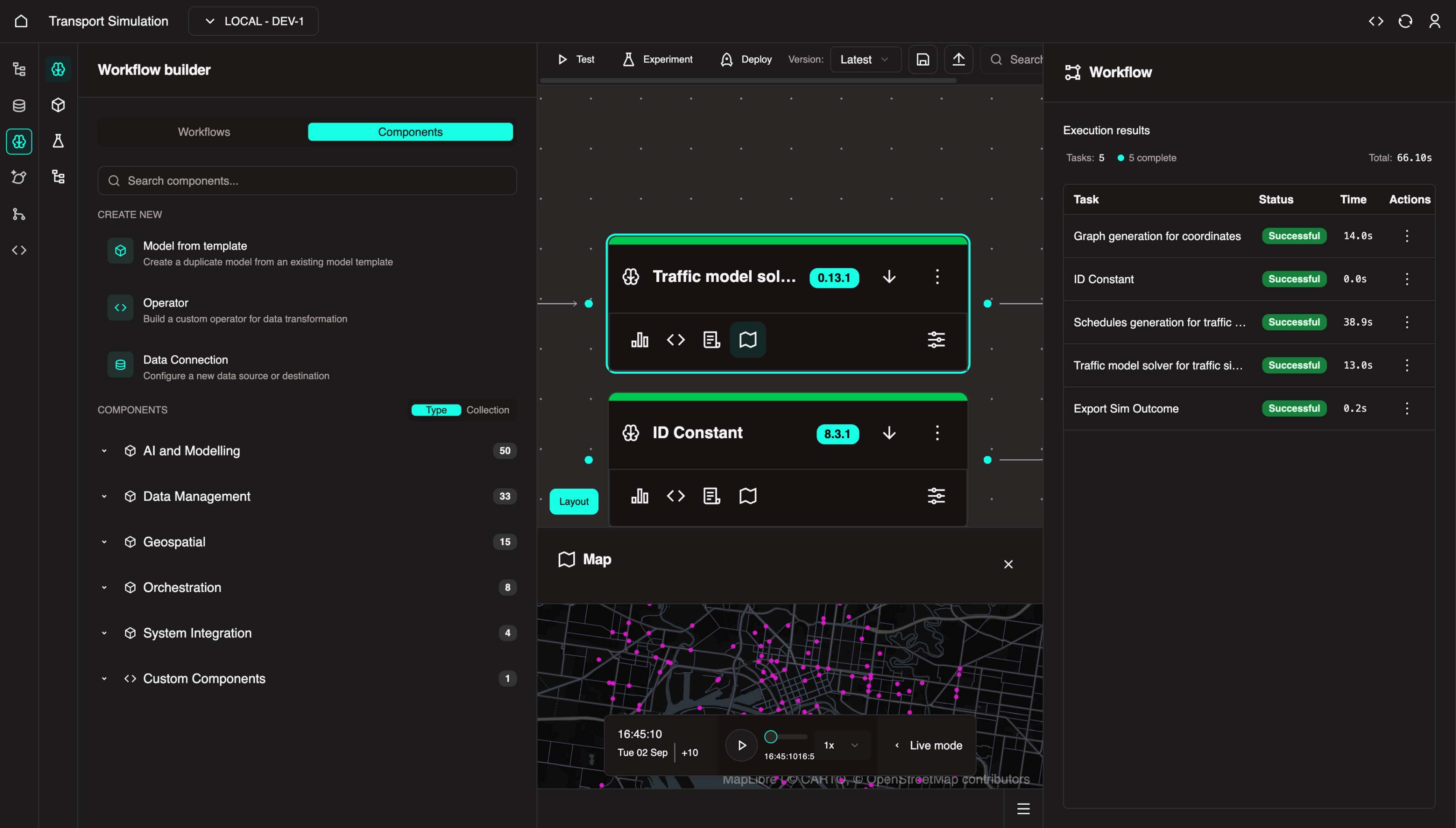
- Click the Map icon and select View Map to see results in a map view.
The map displays the 200 vehicles configured with Melbourne coordinates and a 10km radius.
Coming Soon
Model Validation and Experiment Manager features for workflow verification are coming soon.
3.4 Mapping Variables
With the workflow in place, map variables to enable dynamic inputs at execution time.
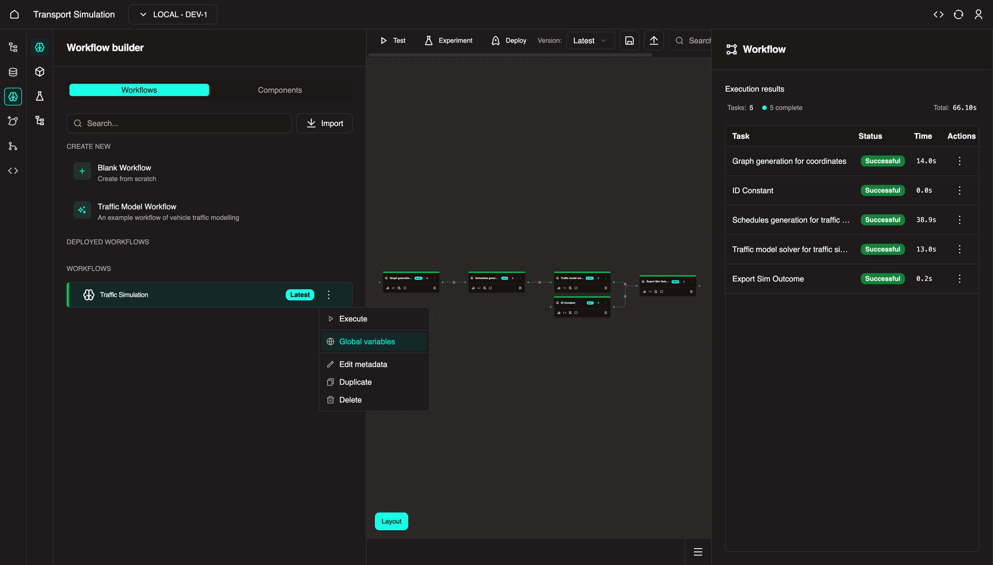
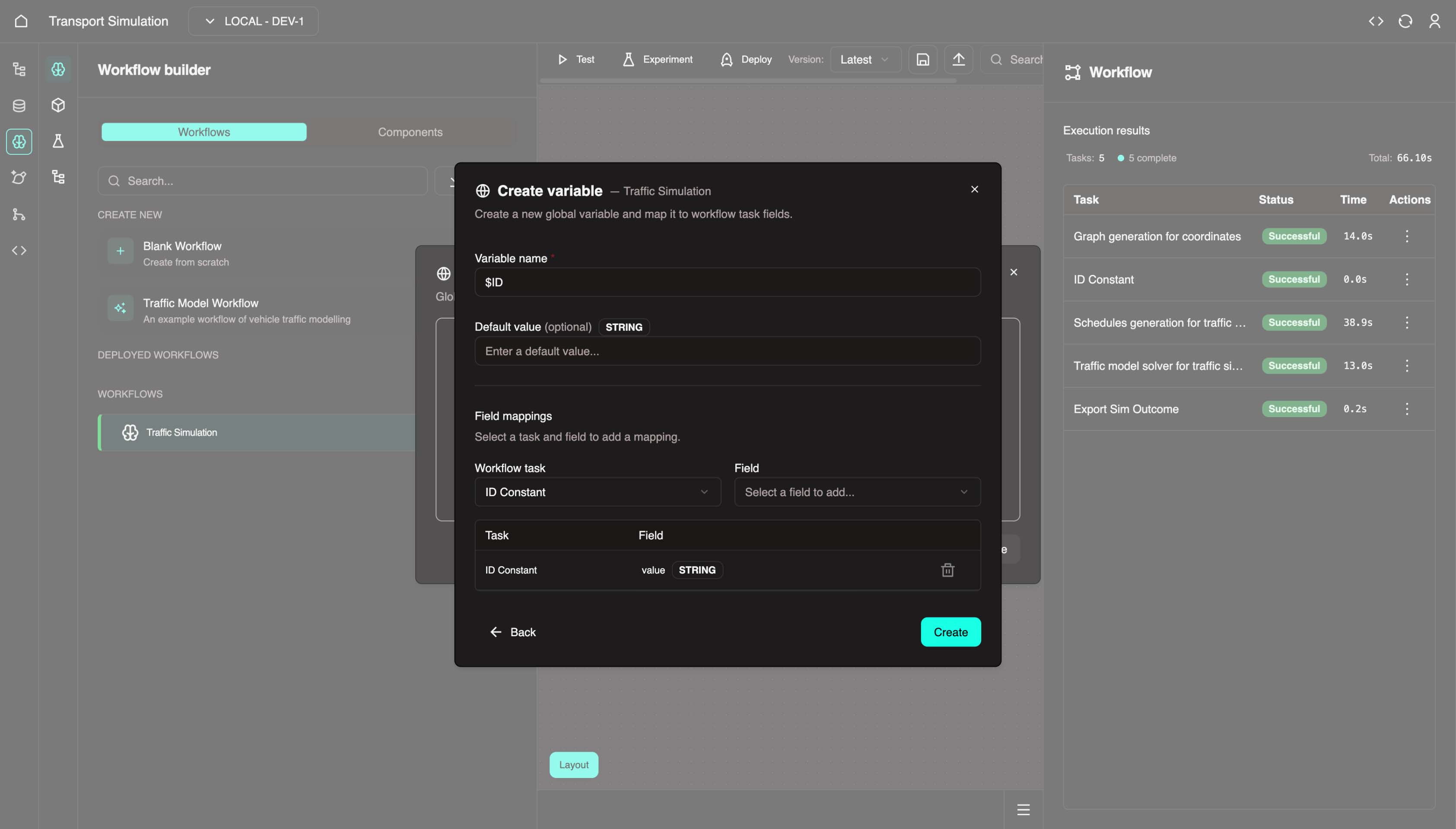
- In the left panel, click the three dots on Traffic Simulation and select Global Variables.
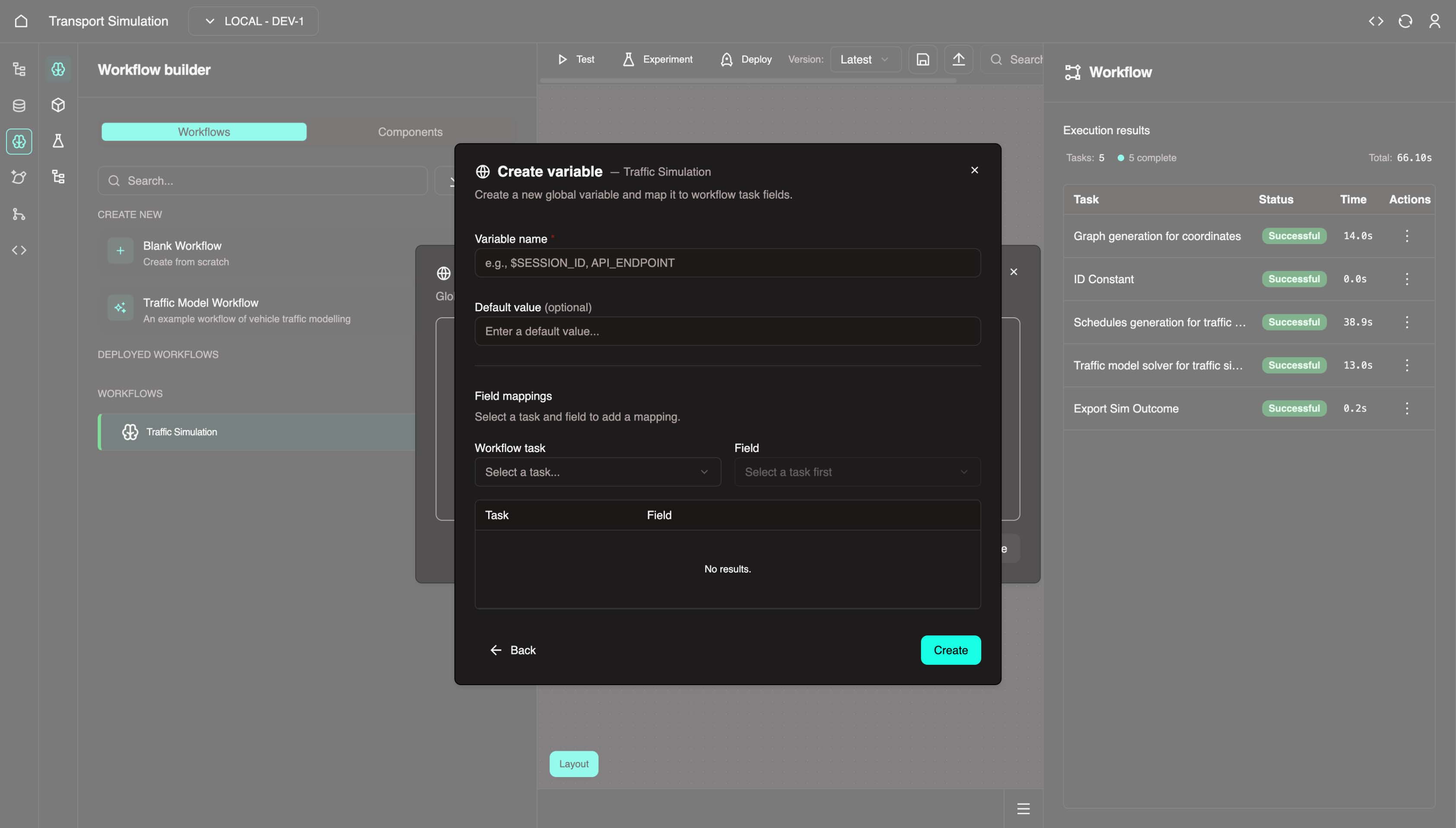
- Create the ID variable:
- Variable Name:
$ID - Workflow Task:
Data Management - Constants - Field:
Value (String) - Click Create
- Variable Name:
- Add variables for the Geospatial - Mapping node. Click Add and create these variables:
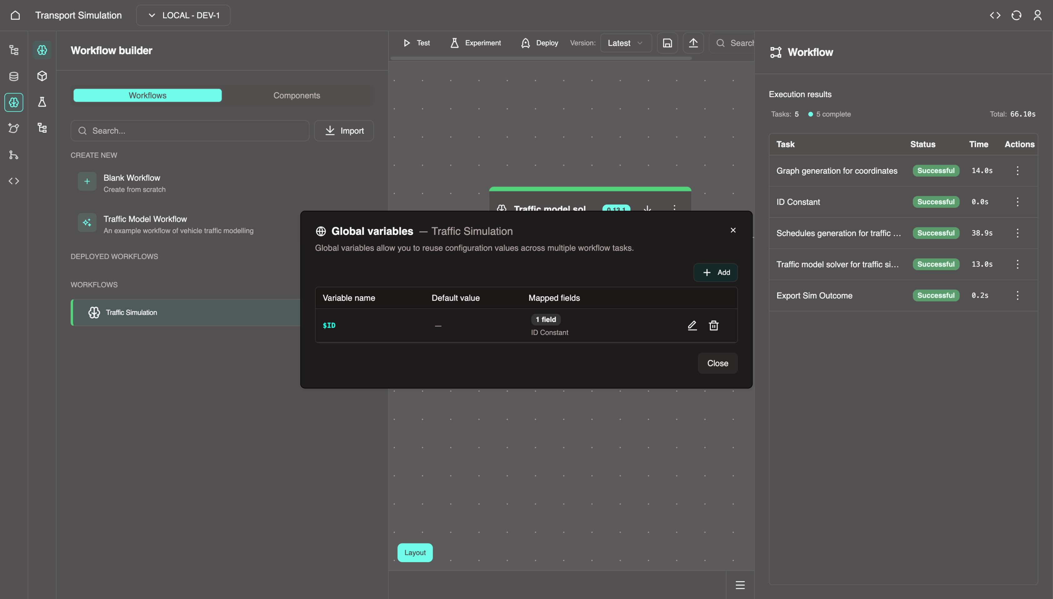
Global Variables
| Variable Name | Workflow Task | Field |
|---|---|---|
$ID | Data Management - Constants | Value (String) |
$LAT | Geospatial - Mapping | latitude |
$LON | Geospatial - Mapping | longitude |
$RADIUS | Geospatial - Mapping | radius |
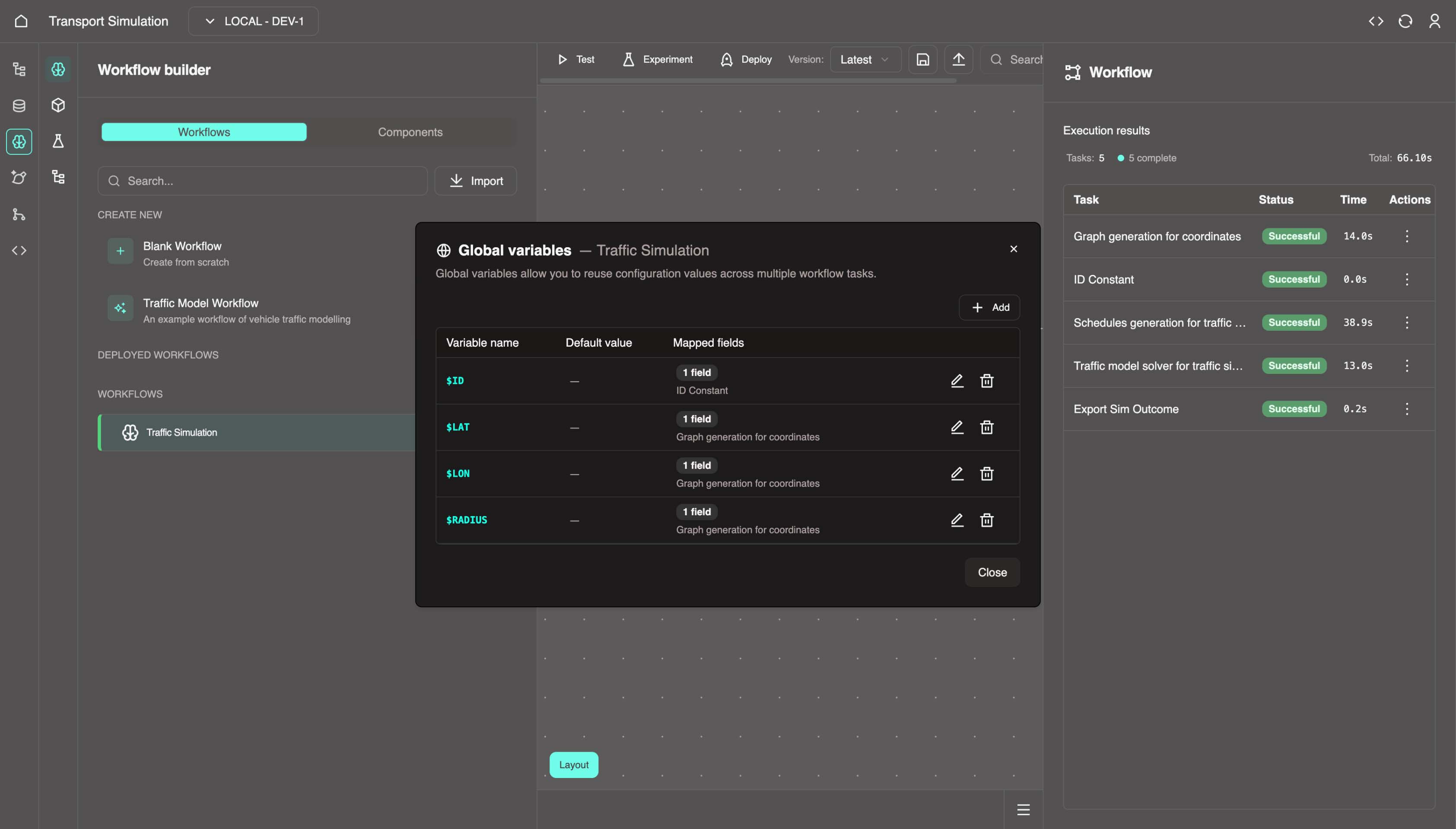
- Click Close to exit the Global Variables panel.
INFO
Mapped variables allow dynamic value substitution at execution time. This is useful for non-static fields. These variables will receive values from the createSimSettings mutation trigger.
3.5 Deploying the Workflow
To use this workflow outside the MDK, you need to deploy it.
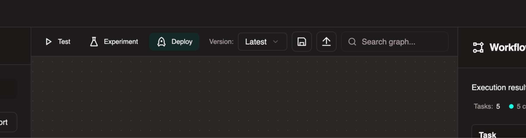
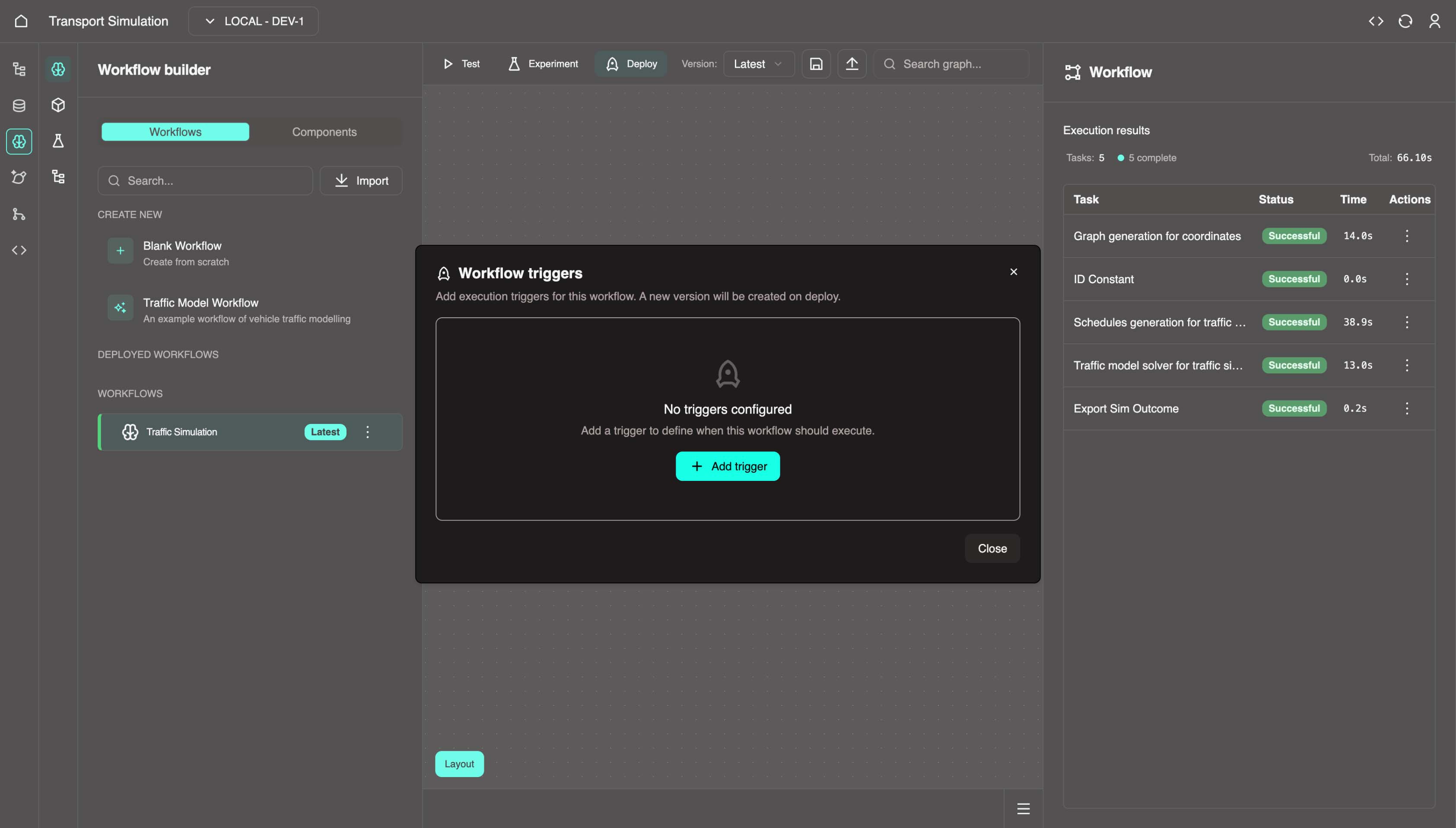
- Click the Deploy button in the top center panel.
- Click +Add trigger.
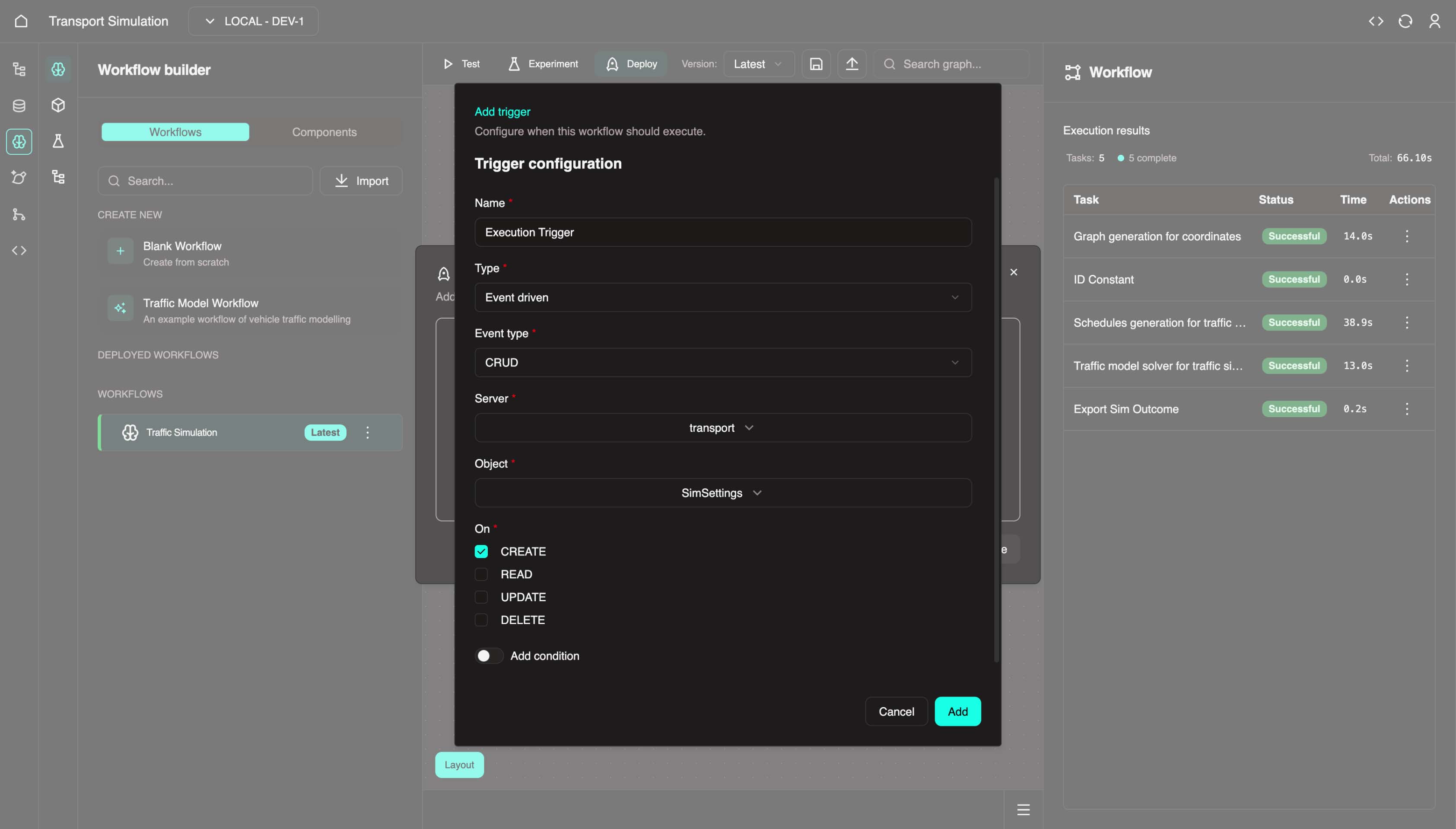
Configure the trigger:
- Name:
Execution Trigger - Type:
Event driven - Event type:
CRUD - Server:
transport - Object:
SimSettings - On: Select CREATE checkbox
- Mapping: Copy and paste the following JSON:
json{ "id": "$ID", "longitude": "$LON", "latitude": "$LAT", "radius": "$RADIUS", "simOutcome": "$<global-var>" }- Name:
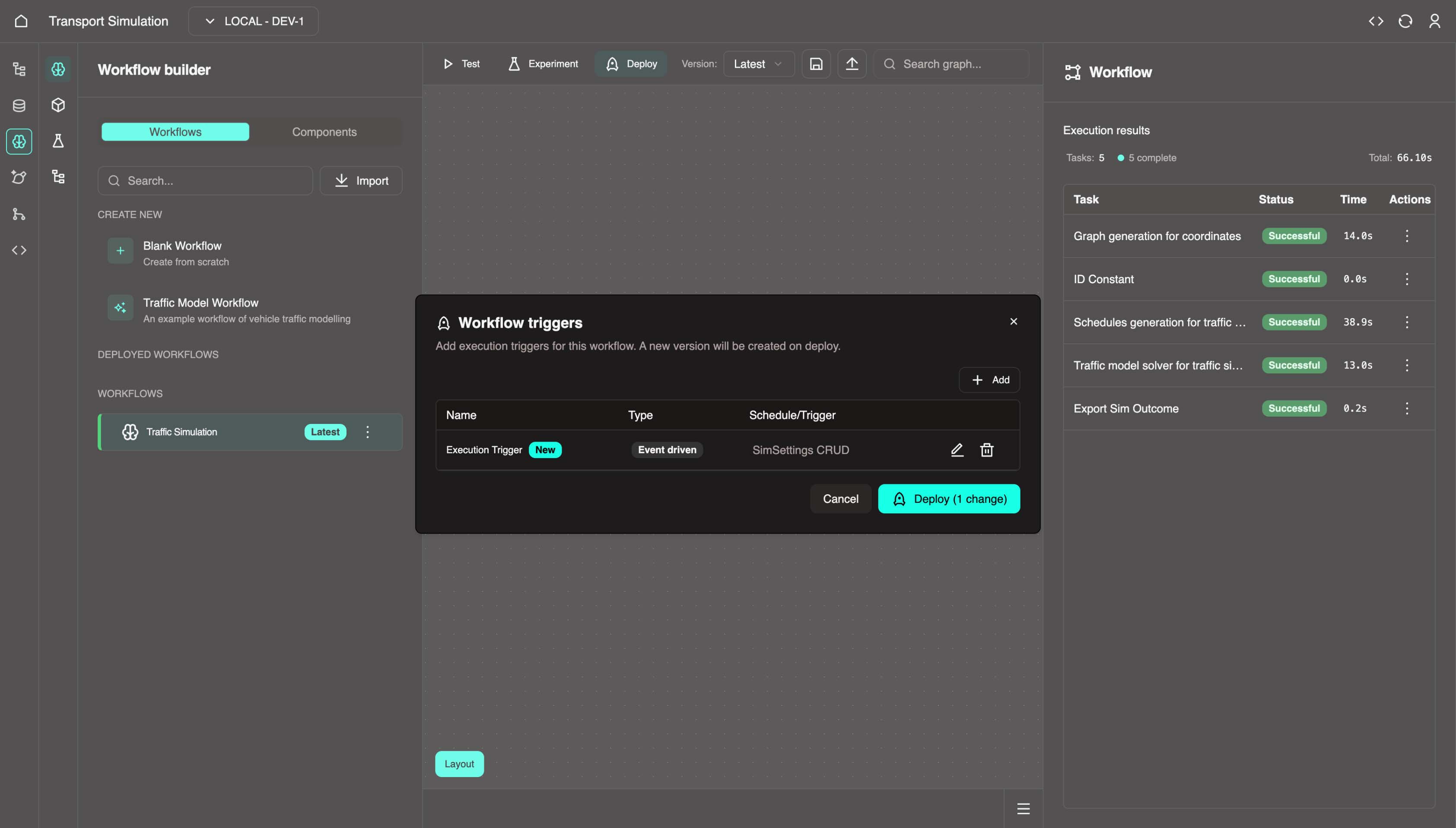
Click Add.
Click Deploy.
- Confirm and click Deploy.
About Deployment Triggers
Deploying a workflow enables execution beyond MDK test mode. This CRUD trigger runs the workflow whenever a SimSettings object is created (via createSimSettings mutation). Other trigger types include:
- Recurring schedule
- Specific timestamp
Once deployed, Traffic Simulation appears under Deployed in the left panel.
🎉 Your workflow is now deployed! Continue to integrate everything in the Frontend Development Kit.
Building Custom Models
You can create your own models using the Model Builder (top left). We support Julia and Python-based models. Your custom models will then appear in the component library.
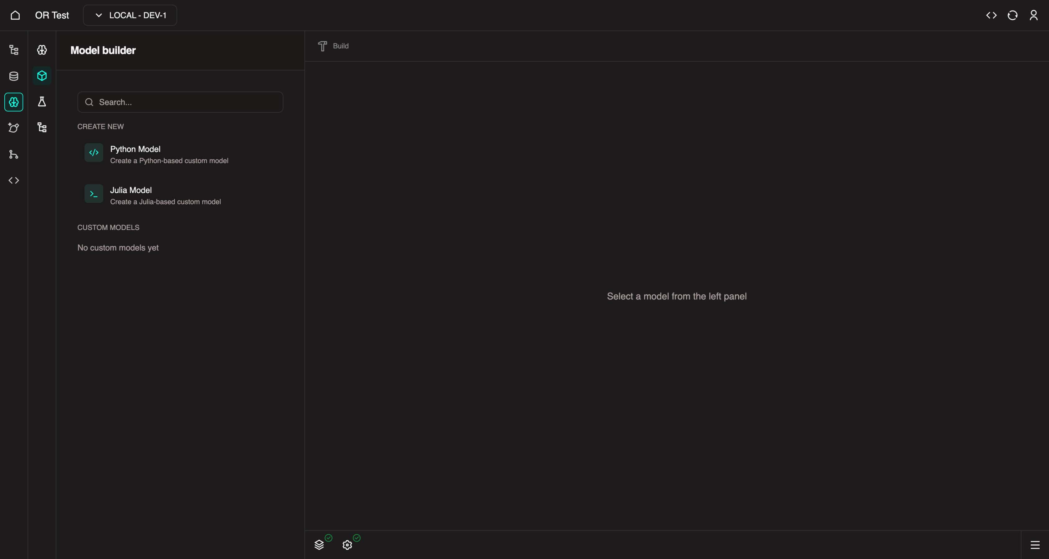
Learn more: Custom BYO Models
Next Steps
Now that your workflow is configured and deployed, you're ready to build the frontend application in the FDK.